- Products
- Products
- Companies
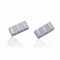
JIAKANG 5245MHz 5G Wifi Dielectric Ceramic Filter

-
Supplier: Zhejiang Jiakang Electronics Co., Ltd. -
Region: Zhejiang, China -
Contact: Ms Sally MA -
Price: $0.30 / >=100 pieces -
Min. Order: 100 pieces
| Payment Terms: | Western Union,T/T,Credit Card; | Packaging Detail: | Pack in tray.; |
| Type: | dielectric filter; | Port: | Shanghai; |
| Insertion loss: | 2.5 max. dB; | Brand Name: | JIAKANG; |
| Application: | Repeater,Signal Amplifier,Mobile Based Mobile Base Stations stations; | Place of Origin: | Zhejiang China; |
| Stopband Attenuation: | 33 min.@ 5490MHz; | 3dB Bandwidth: | 5150-5340 MHz; |
| Nominal Center Frequency: | 5245MHz; | Supply Ability: | 1000000 Piece/Pieces per Month; |
| Insertion Loss: | 2.5 max. dB; | Input Impedance: | 50Ω; |
| Size: | 8.6*5*3mm; | Stopband attenuation: | 33 min.@ 5490MHz,36 min.@ 5530MHz,40 min.@ 5610MHz; |
| Center frequency: | 5245MHz; | Model Number: | DFC0304R5245P190 A10-R1; |
| Bandwidth: | 5150-5340 MHz; | Transfer Function: | Band Pass; |
You are here:Home >> Dielectric Antennas&filters > Dielectric Filters&duplexer > Dielectric Filter>>
5245MHz 5G Wifi Dielectric Ceramic Filter
![]()
|
DFC0304R5235P180A10 and DFC0304R5697P360A10 are usually used as a pair;5245M and 5665M are in a pair. |

| ELECTRICAL SPECIFICATIONS | ||||||||||||||||||
|
RATING |
||||||||||||||||||
|
||||||||||||||||||
|
ELECTRICAL SPECIFICATIONS |
||||||||||||||||||
|
|
Dimensions and mark |
|
|
|
RECOMMENDED PC BOARD PATTERN |
|
|
|
CHARACTERISTIC CURVE |
|
|


![]()
|
||||||||||||||||||||||||||||||||||||
| Table 1 | ||||||||||||||||||||||||||||||||||||
|
||||||||||||||||||||||||||||||||||||
| Recommended soldering conditions | ||||||||||||||||||||||||||||||||||||
|
|
||||||||||||||||||||||||||||||||||||
|
PACKAGE |
||||||||||||||||||||||||||||||||||||
|
Inner Box Dimensions
|
||||||||||||||||||||||||||||||||||||
|
||||||||||||||||||||||||||||||||||||


Click for more information
|
Our microwave dielectric products mainly include dielectric patch antennas, filters, duplexers and GPS modules, which are widely used for positioning, satelliate broadcasting receiver system,RFID,ETC and so on. We are dedicated in the development of core technologies and have achieved the leading position in the ceramic powder formula,manufacturing processes and test technologies. Some products and processes are authorized national patents.Customized products are available.
Memo: Above specification subject to change without further notice.Please contact us for more details. |
Click for more information

Q1:Are you a manufacturer or a trading company?
A1: We have been specialized in the piezo ceramic related products manufacturing for 31 years.
Q2:Where is your factory located?
A2: Factory address: No.1188,Jiahang Road,Jiaxing City , Zhejiang Province,China.
Q3: What's your company MOQ?
A3: Small quantity also available.
Q4: What's the payment way?
A4: T/T, western union, credit card etc.
Q5: Can you send a sample for us to test ?
A5: Yes, most samples are available for free. For samples whose cost is very high, the sample fee will return back in future order.
Q6:What is your shipping way?
A6: We support DHL, UPS, FedEx, EMS.

-
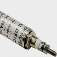
700 MHz RF Cavity Band Stop Filter, N Female for IBS BTS DAS

-
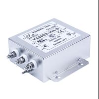
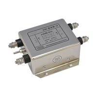
YX84G3-30A-S EMI filter three-phase power line filter 30A high current 520V inverter RFI filter
-
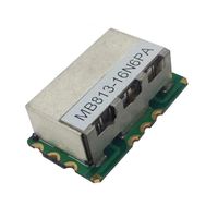
Jiakang Internet of Vehicles Communication Signal Amplifier High Dielectric Material
-
250VAC 16A feedthrough electromagnetic filter mri faraday cage
-
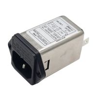
IEC 320 C14 Male Plug YL-T1-2F Fused Power EMI Filter
-
UGwave OEM ODM Radio Channel Rf Dielectric Ceramic 836.5 MHz Low Pass Filter Bandpass Filter 2kw
-
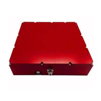
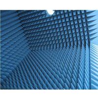
EMI/Rfi shielding, radar absorbers, microwave anechoic chambers
-
40A 250V AC noise suppressor emi filter for converters
-
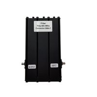
380~520 MHz RF band cavity filter, female sma
-
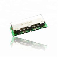
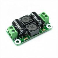
0-50V 4A DC Power Filter Board Class D Power Amplifier Interference Suppression Board Automotive Industrial Control Board
Other Products
-
$1.50 - $2.50 / piece
-
$1.50 / piece
-
$0.90 / piece
-
$0.06 / piece
-
$1.50 / piece
-
$0.30 / piece
-
$0.50 / piece