- Products
- Products
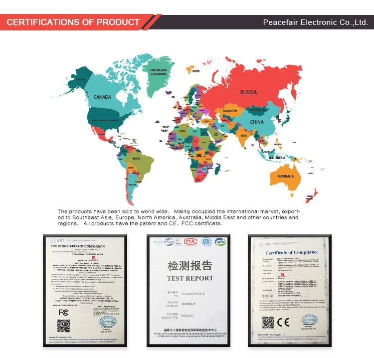
- Companies
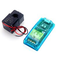
2018 Latest DC 0-300V 100A Modbus RTU Solar Power Meter Energy Meter RS485 With 100A shunt and USB Cable

-
Supplier: Ningbo Peacefair Electronic Technology Co., Ltd. -
Region: Zhejiang, China -
Price: $9.50 / >=2 pieces -
Min. Order: 2 pieces
| Display Type: | Digital Only; | Accuracy Class: | 1.0grade; |
| Current test range: | 0.02-300A; | Voltage resolution: | 0.01V; |
| Communication: | RS485 Port MODBUS-RTU Protocol; | Energy resolution: | 1wh; |
| Single package size: | 14X11X4 cm; | Measuring Energy Range: | 0-9999KWH; |
| Power resolution: | 0.1W; | Place of Origin: | Zhejiang China; |
| Certificate: | CE FCC; | Dimensions: | 90*60.5*23mm(L*W*H); |
| Single gross weight: | 0.24 KG; | Power test range: | 0.2-90kW; |
| Energy test range: | 0-9999kwh; | Voltage test range: | 0.05-300V; |
| Accessory: | 100A shunt+USB cable; | Packaging Detail: | The size of the inner carton:14*11*4cm The size of outside carton:46*38*38cm(100pcs/one carton); |
| Selling Units: | Single item; | Output Voltage: | 0.05-300V; |
| Model Number: | PZEM-017; | Brand Name: | Peacefair; |
| Operating Temperature: | -20'C ~ +60'C; |


Title goes here.
Overview
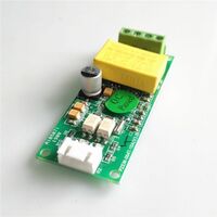
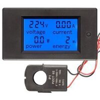
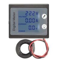
This document describes the specification of the PZEM-003/017 DC communication module, the module is mainly used for measuring DC voltage, current, active power, frequency and energy consumption, the module is without display function, the data is read through the RS485 interface.
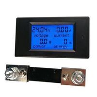
PZEM-003: Measuring Range 10A (Built-in Shunt)
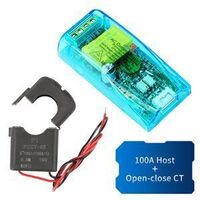
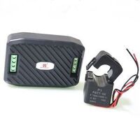
PZEM-017: Measuring Range 50A,100A,200A,300A (the current range is depend on the external shunt specification )
1. Function description
1.1 Voltage
1.1.1 Measuring range:0.05-300V. (when the test voltage is <7V, please use the independent power supply mode)
1.1.2 Resolution:0.01V.
1.1.3 Measurement accuracy:1%.
1.2 Current
1.2.1 Measuring range:0.01-10A(PZEM-003);0.02-300A(PZEM-017;can be matched with 50,100,200,300A four kinds of shunt).
1.2.2 Resolution:0.01A
1.2.3 Measurement accuracy:1%
1.3 Power
1.3.1 Measuring range:0.1-3kW(PZEM-003);0.2-90kW(PZEM-017)
1.3.2 Resolution: 0.1W
1.3.3 Measurement accuracy:1%
1.4 Energy Consumption
1.4.1 Measuring range: 0-9999kWh
1.4.2 Resolution: 1Wh
1.4.3 Measurement accuracy:1%
1.4.4 Reset energy: use software to reset.
1.5 Over Voltage alarm
Voltage threshold can be set, divide into high voltage and low voltage threshold, when the measured voltage exceeds the threshold, it can alarm
The default high voltage threshold is 300V, the default low voltage threshold is 7V.
1.6 Communication interface
RS485 interface.
2. Communication protocol
2.1 Physical layer protocol
Physical layer use UART to RS485 communication interface.
Baud rate is 9600, 8 data bits, 2 stop bit, no parity.
2.2 Application layer protocol
The application layer use the Modbus-RTU protocol to communicate. At present, it only supports function codes such as 0x03 (Read Holding Register), 0x04 (Read Input Register), 0x06 (Write Single Register), 0x41 (Calibration), 0x42 (Reset energy).etc.
0x41 function code is only for internal use (address can be only 0xF8), used for factory calibration and return to factory maintenance occasions, after the function code to increase 16-bit password, the default password is 0x3721.
The address range of the slave is 0x01 ~ 0xF7. The address 0x00 is used as the broadcast address, the slave does not need to reply the master. The address 0xF8 is used as the general address, this address can be only used in single-slave environment and can be used for calibration etc.operation.
2.3 Read the measurement result
The command format of the master reads the measurement result is(total of 8 bytes):
Slave Address + 0x04 + Register Address High Byte + Register Address Low Byte + Number of Registers High Byte + Number of Registers Low Byte + CRC Check High Byte + CRC Check Low Byte.
The command format of the reply from the slave is divided into two kinds:
Correct Reply: Slave Address + 0x04 + Number of Bytes + Register 1 Data High Byte + Register 1 Data Low Byte + ... + CRC Check High Byte + CRC Check Low Byte
Error Reply: Slave address + 0x84 + Abnormal code + CRC check high byte + CRC check low byte
Abnormal code analyzed as following (the same below)
0x01,Illegal function;
0x02,Illegal address;
0x03,Illegal data;
0x04,Slave error.
The register of the measurement results is arranged as the following table
Register address Description Resolution
0x0000 Voltage value 1LSB correspond to 0.01V
0x0001 Current value 1LSB correspond to 0.01A
0x0002 Power value low 16 bits 1LSB correspond to 0.1W
0x0003 Power value high 16 bits
0x0004 Energy value low 16 bits 1LSB correspond to 1Wh
0x0005 Energy value high 16 bits
0x0006 High voltage alarm status 0xFFFF is alarm,0x0000 is not alarm
0x0007 Low voltage alarm status 0xFFFF is alarm,0x0000 is not alarm
For example, the master sends the following command (CRC check code is replaced by 0xHH and 0xLL, the same below):
0x01 + 0x04 + 0x00 + 0x00 + 0x00 + 0x08 + 0xHH + 0xLL
Indicates that the master needs to read 8 registers with slave address 0x01 and the start address of the register is 0x0000.
The correct reply from the slave is as following:
0x01 + 0x04 + 0x10 + 0x27 + 0x10 + 0x00 + 0x64 + 0x03 + 0xE8 + 0x00 + 0x00 + 0x00 + 0x00 + 0x00 + 0x00 + 0x00 + 0x00 + 0x00 + 0x00 + 0xHH + 0xLL
The above data shows
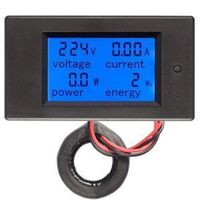
Voltage is 0x2710,converted to decimal is 10000,display 100.00V;
Current is 0x0064,converted to decimal is 100,display 1.00A;
Power is 0x000003E8,converted to decimal is 1000,display 100.0W;
Energy is 0x00000000,converted to decimal is 0,display 0Wh;
High voltage alarm status 0x0000,indicates the current voltage is lower than the high voltage threshold.
Low voltage alarm status 0x0000,indicates the current voltage is higher than the low voltage threshold.
2.4 Read and modify the slave parameters
At present,it only supports reading and modifying slave address and power alarm threshold
The register is arranged as the following table
Register address Description Resolution
0x0000 High voltage alarm threshold(5~350V),default is 300V 1LSB correspond to 0.01V
0x0001 Low voltage alarm threshold(1~350V),default is 7V 1LSB correspond to 0.01V
0x0002 Modbus-RTU address The range is 0x0001~0x00F7
0x0003 The current range(only for PZEM-017) 0x0000:100A
0x0001:50A
0x0002:200A
0x0003:300A
The command format of the master to read the slave parameters and read the measurement results are same(described in details in Section 3.3), only need to change the function code from 0x04 to 0x03.
The command format of the master to modify the slave parameters is (total of 8 bytes):
Slave Address + 0x06 + Register Address High Byte + Register Address Low Byte + Register Value High Byte + Register Value Low Byte + CRC Check High Byte + CRC Check Low Byte.
The command format of the reply from the slave is divided into two kinds:
Correct Response: Slave Address + 0x06 + Number of Bytes + Register Address Low Byte + Register Value High Byte + Register Value Low Byte + CRC Check High Byte + CRC Check Low Byte.
Error Reply: Slave address + 0x86 + Abnormal code + CRC check high byte + CRC check low byte.
For example, the master sets the slave's high voltage alarm threshold:
0x01 + 0x06 + 0x00 + 0x01 + 0x4E + 0x20 + 0xHH + 0xLL
Indicates that the master needs to set the 0x0001 register (low voltage alarm threshold) to 0x4E20(200.00V).
Set up correctly, the slave return to the data which is sent from the master.
For example, the master sets the low voltage alarm threshold of the slave
0x01 + 0x06 + 0x00 + 0x02 + 0x03 + 0xE8 + 0xHH + 0xLL
Indicates that the master needs to set the 0x0002 register (low voltage alarm threshold) to 0x03E8(10.00V).
Set up correctly, the slave return to the data which is sent from the master.
For example, the master sets the address of the slave
0x01 + 0x06 + 0x00 + 0x03 + 0x00 + 0x05 + 0xHH + 0xLL
Indicates that the master needs to set the 0x0003 register (Modbus-RTU address) to 0x0005
Set up correctly, the slave return to the data which is sent from the master.
2.5 Reset energy
The command format of the master to reset the slave's energy is (total 4 bytes):
Slave address + 0x42 + CRC check high byte + CRC check low byte.
Correct reply: slave address + 0x42 + CRC check high byte + CRC check low byte.
Error Reply: Slave address + 0xC2 + Abnormal code + CRC check high byte + CRC check low byte
2.6 Calibration
The command format of the master to calibrate the slave is (total 6 bytes):
0xF8 + 0x41 + 0x37 + 0x21 + CRC check high byte + CRC check low byte.
Correct reply: 0xF8 + 0x41 + 0x37 + 0x21 + CRC check high byte + CRC check low byte.
Error Reply: 0xF8 + 0xC1 + Abnormal code + CRC check high byte + CRC check low byte.
It should be noted that the calibration takes 3 to 4 seconds, after the master sends the command, if the calibration is successful, it will take 3 ~ 4 seconds to receive the response from the slave.
2.7 CRC check
CRC check use 16bits format, occupy two bytes, the generator polynomial is X16 + X15 + X2 +1, the polynomial value used for calculation is 0xA001.
The value of the CRC check is all results of a frame data checking divide CRC


-
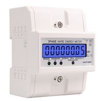
DDS024 230V/400V 50Hz DDS024 Three Phase Display Backlit Household 380V Rail Type 4P Electric Meter 5-80

-
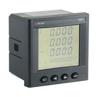
power meter manufacturer AMC96L-E4/KC ac alarm voltmeter with rs485 power monitoring
-
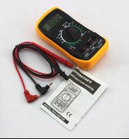
Multimeter XL830L Digital multimeter 830L Digital multimeter
-
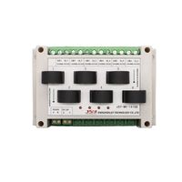
Factory direct sales intelligent multi-channel electronic watch strap RS485 communication power meter
-
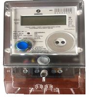
Manufacturer KHLSM Single Phase Electrometer Somali Type
-
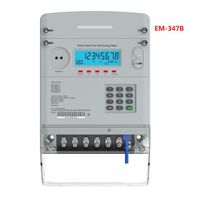
ROBUSYS EM-347B Three-phase STS keyboard prepaid electricity meter with narrow PLC and optical port
-
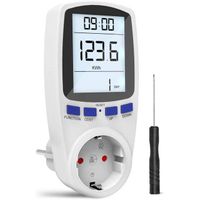
Energy Analyzer with Digital Power Meter/Energy Cost Meter/Power Meter Outlet with Backlight
-
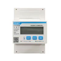
Hot sale CHINT DTSU666 RS485 220V/380V 5-80A electric energy meter intelligent digital display three-phase microelectronics
-
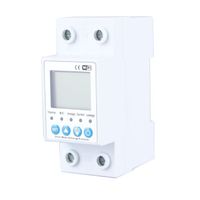
HMONOFF 63A TUYA APP intelligent circuit leakage over-voltage protector relay equipment switch circuit breaker energy power kWh meter
-
SMT JUKI 740 Laser KE740 KP620 PM570 Cyberoptics 6604097
Other Products
-
$6.80 - $8.30 / unit
-
$6.00 - $7.80 / unit
-
$4.00 - $5.50 / unit
-
$7.00 / unit
-
$7.30 / piece
-
$7.65 / piece
-
$9.10 / piece
-
$7.50 / unit
-
$8.00 / unit
-
$8.00 / piece