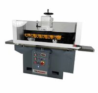
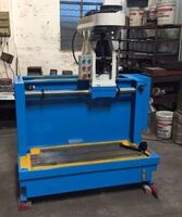
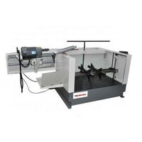
- Products
- Products
- Companies
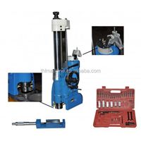
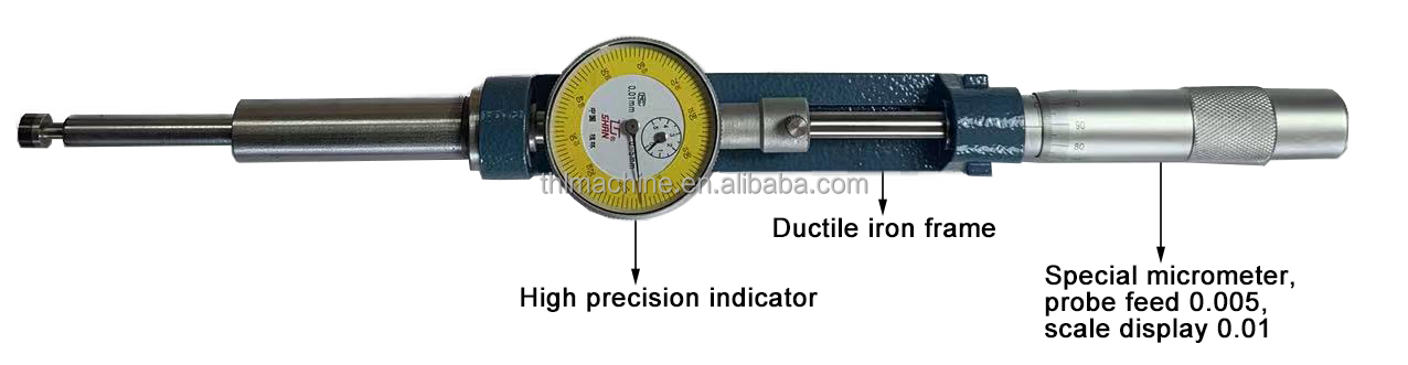
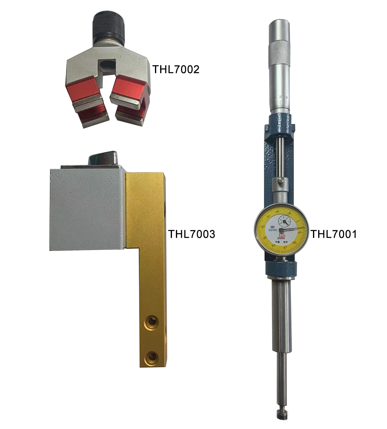
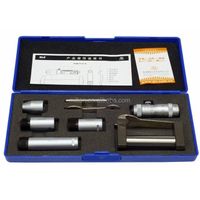
Magnetic base tool setting micrometer

-
Supplier: Shanghai THL Machine Tool Co., Ltd. -
Region: Shanghai, China -
Contact: Mr xu li -
Price: $50.00 /unit -
Min. Order: 1 unit
| Warranty: | 1 | port: | Shanghai |
| payment terms: | wire transfer | Supply capacity: | 1 unit per day |
| brand: | THL machine | Packaging Details: | Box |
| Certification: | other | Origin: | China Shanghai |
| model: | THL7001 |
Tool setting micrometer with magnetic base
Dial gauge with micrometer and magnetic base
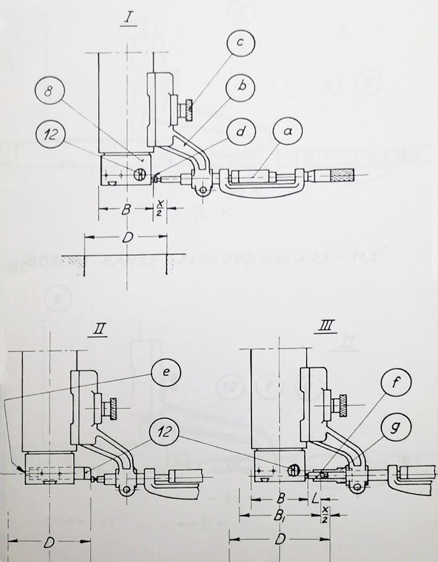
Tool setting (Figure No. 4C-6)
The tool setting micrometer (a) fits in the tool holder (b) and is fixed to the boring spindle by a screw (C).
Next, place the contact point of the micrometer on the measuring point (a) on the boring head and set the micrometer and gauge to zero.
For tool setting, we now start with the basic dimensions of the boring head, ie. 1.75", 2.35" and 3.55" (46, 60 and 90 mm). See Fig. 1.
The difference between the desired cylinder diameter (D) and the basic dimension (B) is the actual dimension (X) to which the micrometer must be set.
After setting, the boring spindle must be turned so that the cutting tool (12) points towards the setting micrometer. See picture. two.
Adjust the cutting tool by screw (e) until the dial points to zero, then secure the cutting tool by the locking screw on the side of the spindle.
If the difference between the desired cylindrical diameter and the basic dimension of the boring spindle used is greater than the range of the micrometer (2" (50 mm)), a gauge block (f) with a length of 3/4" must be used (17.5 mm).
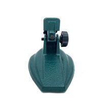
as. As shown in Figure III, the gauge block is guided by a bracket (g) that must be mounted on the micrometer. When set to zero, base size (B1) will be equal to base size (B)
The diameter of the spindle plus 1.1/2" (35 mm), the gauge block and its holder can then be removed and the cutting tool set up as above.
Readjust the basic dimensions of the boring shaft.
(Picture No. 4C-6)
The inaccuracy of the boring may be due to the shock to the measurement point (d) on Figure 4C-6 during the spindle change.
If f. graduate School. No. 2 boring spindle needs to be readjusted, and this spindle needs to be used for boring. Then measure the borehole diameter very precisely, if the measurement is f.inst. 80.96 mm (3. 19"), the hole diameter minus the basic dimension (B), that is, 80. 96 minus 60=20.96mm (3.19"-2.35"=0.84").
Now the tool setting micrometer (a) is adjusted to 20. 96 mm (0. 84") and placed in the tool holder (b) which is fastened to the spindle.
The contact point of the tool micrometer (a) should be in contact with the cutting tool (12) so that the dial reads zero.
Then fix the micrometer on the bracket.
Now turn the boring spindle so that the contact point of the setting micrometer points to the measuring point (d) and now turn the micrometer screw to the zero position. Then loosen the measuring point (d) with the screw on the bottom of the spindle and adjust this measuring point until the dial of the micrometer shows zero, then tighten the contact point.
Boring axes will now have the correct base dimensions.
The above steps should also be followed for other spindles.
The basic dimensions (B) of the boring shaft are as follows:
No. 1 spindle 46 mm. 1,8" = 45,72 mm.
No. 2 spindle 60 mm. 2.35 inches = 59.69 millimeters.
No. 3 spindle 90 mm. 3,55" = 90,17 mm.
140mm. 5,50" = 139,70 mm.
No. 4 spindle 140mm. 5,50" = 139,70 mm.
190 mm. 7,50" = 190,50 mm
Boring head 300mm. 11 ,90” = 302,26 mm.


packaging and delivery
Packaging Details: Boxed
Port: Shanghai
delivery time:
|
Quantity / piece) |
1 - 100 |
>100 |
|
EST. time (days) |
15 |
to be negotiated |
-
Link 100-125mm screw outer diameter micrometer, thread micrometer

-
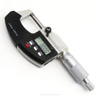
0-25mm tool outer diameter micrometer, high-precision digital micrometer thickness gauge, spiral micrometer
-
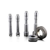
Xibei brand 50-175mm inner diameter micrometer combination extension rod
-
Precision Micrometer Bracket Base Digital Micrometer Bracket External Micrometer Bracket
-
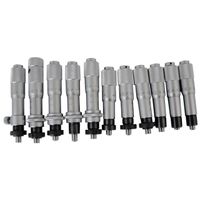
Custom high-precision micrometer head 0-25mm 25-50mm 50-75mm 75-100m micrometer head
-
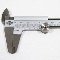
KANON Flat Calipers
-
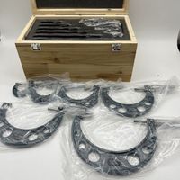
Micrometer set wooden box packaging 6PCS micrometer set 0-150mm arch frame Mitutoyo type micrometer set
-
Best Selling Three-Point Inner Micrometer Digital Display Height Gauge
-
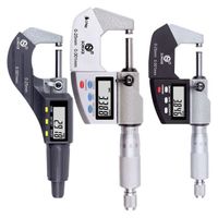
0-25MM/0-1" 2-way electronic digital display external micrometer with laser scale
-
High-precision measuring tool three-point inner diameter micrometer 16-20mm 50-63mm three-claw inner diameter micrometer set 50-100mm
Other Products
-
$1125.00 / unit
-
$200.00 / unit
-
$1400.00 / unit
-
$810.00 / unit
-
$6000.00 / unit
-
$2900.00 / unit
-
$5000.00 / unit