- Products
- Products
- Companies
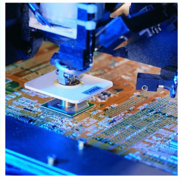
PCB Manufacturer CC CV DC DC Wind Solar Battery MPPT Charger 5-78V to 2-78V 12.6V DC 20A Automatic Buck/Boost Buck/Boost

-
Supplier: SHEN ZHEN HELLO CHIP ELECTRONIC COMPANY LIMITED -
Region: Guangdong, China -
Contact: Mr Allen Chan -
Price: $0.10 /piece -
Min. Order: 1 piece
| model: | MSAD23 | application: | Solar Power System Home |
| port: | Shenzhen or Hong Kong or Guangzhou | brand: | US ZTE |
| payment terms: | L/C, D/A, D/P, T/T, Western Union, MoneyGram, Paypal | Supply capacity: | 1,000,000 pieces per month |
| Shipping Details: | 3~7 days | Serve: | Accept OEM customized service |
| weight: | 500 g | exhibit: | to lead |
| Output Power: | 2000W max | Protect: | Overcurrent/short circuit protection |
| Conversion efficiency: | 97% max | Origin: | Guangdong, China |
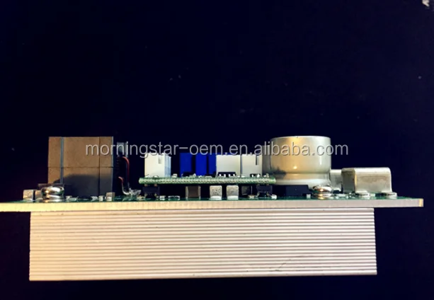
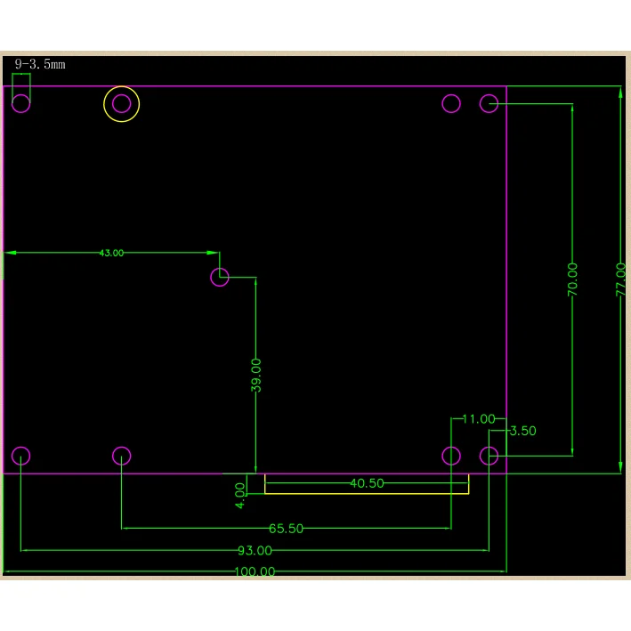
| Packaging Details: | 10*7*8CM | size: | 100*81*21mm |
| The output voltage: | DC 2-78V (adjustable) | type: | DC/DC Converter |
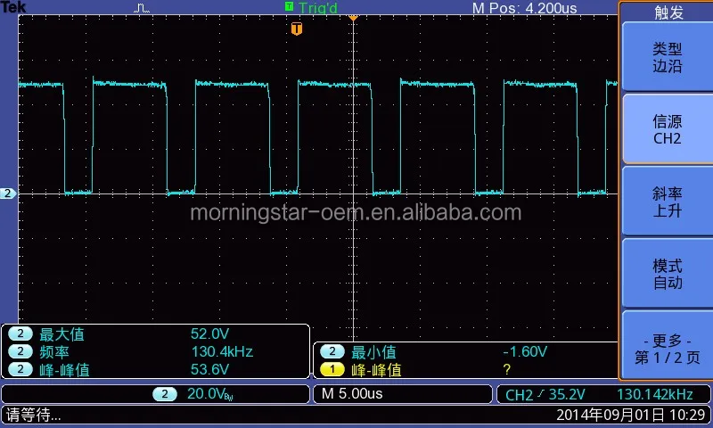
| Output frequency: | 200KHZ | Output current: | 0-20A (adjustable) |
| Output waveform: | ≤ 50 mV | output type: | single |
| Input voltage: | DC 5-78V |
*We produce modules!
*Customization is possible! !
*Our company manufactures your own boards! ! !
5-78V to 2-78V 20A DC-DC auto boostBuck Boost Converter Wind MPPTSolar Charge Controller Module
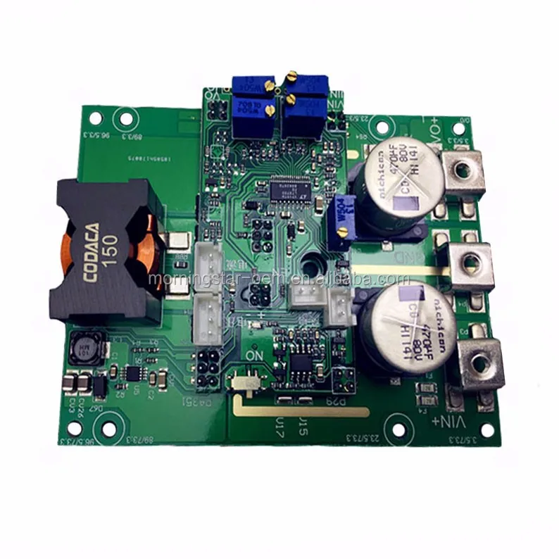
New input and output voltage and current switching display, input and output dual fuses, four boards plus perfect GND layout design, optimized inductor peak voltage; 40V increased to 63V/10A, and the overall efficiency reached 94.8%. Input to 75V, internal four-circuit working status LED display)
About optional parameters: the default shipment input is 75V, the output is 60V version, and the output is only 72V, you need to contact
The default mode of operation is intermittent (see note)
The default operating frequency is 120KHZ, which requires fast response to adjustable high frequency, but it will bring low efficiency.
Input and output can be set as required.
Supplementary note:
1. Linear Technology LT8705 synchronous rectification automatic step-down control scheme
2. Capacitors need to be replaced for versions with output higher than 60V, and the filter is relatively poor. Previously, 75V could not come out because the output is higher than 65V and the frequent full-load startup has a certain probability of burning the chip.
3. Adjustable range of input voltage: According to the recommendation of 18V, 36V and other panels, it should be set above 16V. This function is suitable for MPPT solar panels. See the operating instructions for details.
4. Voltage display: The voltmeter head can measure a maximum voltage of 100V, and the green multimeter has an error of about 0.5V relative to the green voltage. (The jumper cap can be used to switch the display input or output, but not at the same time)
5. Current display (optional): The maximum current measurement is 30A, the accuracy is about 0.02A-0.3A, the accuracy will vary in different use environments, the current display is only for output reference, please do not evaluate the ammeter standard, 3 milliohm high-end sampling resistor 20A shows that this value is already ok, and it is better than some general multimeters in the case of high current display. The display is calibrated with a green multimeter. (The jumper cap can be used to switch the display input or output, but not at the same time)
6. Module recommended parameters: input voltage below 75V (limit test input 85V), output voltage below 60V. The input and output current is within 15A. The boost pressure difference is less than 3, which has good reliability and stability. The premise is to ensure the heat dissipation of the module.
Module advantages:
1. It has a high input working voltage of more than 75V, can withstand 80V pulse voltage, and can withstand the pulse voltage when starting up. (Controller voltage 80V, MOS tube rated 80V)
2. Large output current: the output current can reach 15A for long-time work, and the maximum current is about 20A
3. Adjustable input and output current: the input current can be adjusted as an input constant current source, and the output current can be adjusted. It is especially suitable for high-current charging of batteries, and high-current charging such as iron-lithium batteries, basically covering all batteries.
4. It has the function of input and output voltage adjustment: the input voltage adjustment is used to track the maximum power point of the solar panel voltage, and to a certain extent achieve the function of maximum power point tracking.
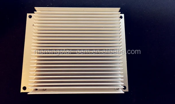
5. It has the function of temperature control fan: the fan starts to rotate when the temperature of the radiator exceeds 45 degrees, and the temperature control part has a hysteresis circuit, so the fan will not vibrate.
6. Anti-irrigation protection: the output terminal can be directly connected to the battery, and the diode cannot be connected in series, which is more lossy than the series diode. The output can withstand 60V pulse voltage. For example, if the output voltage is 14V, 60V DC voltage can be added to the output terminal without worrying about backfeeding.
7. Optional low no-load current mode: input 58.8V and output 14V without access, the standby current is only 8mA, and the 8mA current is directly connected to the 100AH battery. Worried about standby loss. The default is a more reliable intermittent work mode, in one case the full range input and output standby current is 15-80mA.
8. High efficiency: Synchronous rectification method, 500W output power efficiency is as high as 95%, and low dropout output efficiency is higher.
9. High reliability: the control device can withstand 80V withstand voltage, a total of 12 TDK ceramic capacitors for input and output, and Japanese black steel and ruby electrolytic capacitors with an ESR value of 28mΩ. SMD components are sprayed with conformal paint, which can effectively improve the resistance to harsh conditions. Environmental capability
10. Optional input and output voltage and current display: the display part is convenient to check the output status.
Precautions:
1. Use the modules according to the basic principle of energy saving, and use them according to the actual situation.
2. It is best to keep the output-to-input ratio stable within 3. The output needs to be 36V, please ensure that the input is above 12V, and the input current for high voltage difference is recommended to be within 10A, or ensure that the module has better heat dissipation. The larger the boost ratio, the faster the efficiency drops.
3. The input and output cannot be overvoltage! Please do not exceed the maximum voltage described by the module, which may cause permanent damage to the module. Please leave a certain margin for actual use. 5 strings of 12V batteries are based on the 70V standard, which is not actually 12V*5=60V
4. Do not reverse the positive and negative input and output! Module input and output with fuse, anti-burning! If the module does not work and does not display if the input is disconnected accidentally, please use a multimeter to test whether the positive and negative input capacitors are short-circuited. If there is no short circuit, congratulations, the module may still be good, and it may only burn the fuse. Just replace the fuse at work, or just skip the fuse.
5. Please pay attention to the arcing problem of high-voltage DC power supply! Input and output capacitor capacity, high-voltage input or high-voltage output, please pay attention to the arcing problem of the DC power supply, and quickly disconnect when testing the high-voltage output load, otherwise the arc will be pulled up and the terminal will be burned black. The arc generated by high temperature, the author actually measured that the output arc of 50V/8A load can burn the copper pillow for about 3 seconds.
6. Generator input filter problem! If the module is input from an alternator, please ensure that the output filter capacitor of the rectifier bridge is large enough, the output voltage of the rectifier bridge is pulsating, and the module works stably.
7. The output should not be short for a short time, the tube will heat up.
8. If the input is higher than 60V, please add a current-limiting circuit or a current-limiting inductor. Otherwise there is a risk of the input capacitor charging the fuse. Such problems are not covered by the warranty.
instruct:
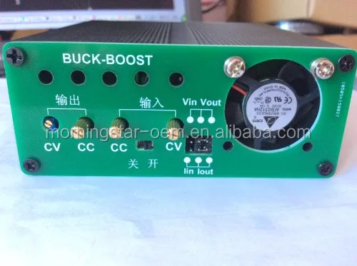
Potentiometer adjustment: (The input and output current adjustment is controlled by the chip, and the adjustment process is based on the nonlinear principle)
The 4 kinds of potentiometer adjustment methods are all clockwise to adjust the value to increase.
1. Input stabilized voltage potentiometer (input CV): Assuming that the minimum input voltage needs to be set to 20V, the adjustment method is to input the terminating 20V power supply, and adjust the potentiometer counterclockwise until the module stops outputting. At this time, it is the 20V undervoltage shutdown value. If the input is a constant current source and the load is large, the module will reduce the input current to maintain the input voltage of 20V.
2. Input current adjustment potentiometer (input CC): Assuming that the maximum input current to be set must not exceed I1, then the input voltage is V1, the output voltage is V2, and the output current is I2. The adjustment method should ensure that V2*I2>I1. Then adjust the potentiometer counterclockwise until I1 is the desired value. For example: set the input current not to exceed 5A, the input voltage is 20V, the output voltage is 20V, and the output current is 6A, then the actual value of the input current is greater than 6A, then adjust the potentiometer counterclockwise until the input current is 5A. Then the input current absorbed by the module in the working state will not be greater than 5A.
3. Output voltage adjustment potentiometer (output CV): adjust the output voltage clockwise to increase, counterclockwise to decrease.
4. Output current adjustment potentiometer (output CC): The adjustment method is to connect the positive and negative of the multimeter and the large load in series at the output terminal (or directly use the multimeter to short-circuit the output, this method is not recommended, and the accuracy will be offset). Adjust the potentiometer counterclockwise, Until the current value of the multimeter drops to the desired value. (The premise of adjustment is that the input power is not limited or the value is greater than the adjustment of the output power, or the correct output value cannot be obtained because the input power is limited) Use the ammeter adjustment method of the module itself to ensure that the output voltage is above 5V, and the output terminal is greater than For the current value required by the heavy load, adjust the potentiometer counterclockwise until the displayed value is the desired value. (Because the output current detection function needs to ensure that the output voltage is above 3V, and the short-circuit output cannot display the output current value after the output voltage is less than 3V).
5. Short-circuit cap switch: The input and output voltage and current of the module are switched and displayed through the jumper cap. Note that the upper and lower rows of pins cannot be connected together, otherwise the ammeter will be burned. The previous row is a voltage switch, and the next row is a current switch.
6. Input and output terminals: high-current copper nose wiring is used when leaving the factory.
application note
1. Maximum solar charging: The input current limiting function is very suitable for constant current source charging of solar panels. It is a good choice to purchase two 200W solar panels plus module charging. The output directly charges the battery, so don't worry about reverse connection and the battery cannot be reversed.
2. High-current and high-efficiency charging of automobile batteries, and charging and power supply systems of automobile secondary batteries
3. Large capacity lithium battery Lithium battery high current constant current charging
4. High power LED constant current drive
5. Battery regulated power supply system, backup voltage regulator for telecommunication base stations.
6. It can be used as a low-demand adjustable voltage regulator (response speed, accuracy, and noise are lower than linear regulators, but with high efficiency and high power characteristics)
7. Other adjustable constant current applications
others:
MPPT function: The module has an input voltage limiting function, that is, to set the maximum solar power generation point voltage. As long as the voltage is lower than this value, the module will reduce the output current and output power to ensure that the input voltage is stable at the set value. For example, the maximum power point voltage of the solar cell is 34V, adjust the input voltage to 34V, and adjust the input voltage potentiometer counterclockwise until the module has no output. At this time, the maximum input voltage for the module to work is 34V.
1. Global delivery: DHL, UPS, FEDEX, EMS, HKPOST, SGPOST, SWPOST
2. Delivery time: 1-2 days. If we don't have stock at that time, it will take 2-4 days to produce it.
1. We accept PAYPAL, TT, WESTERN UNION, ESCROW
2. Commission:
*PayPal: total amount*0.041
*Escrow: total amount*0.05
*Wire transfer: $28-$45 (depending on amount)
*Western Union: $0

-
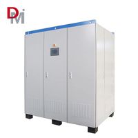
1000w to 10kw wind turbine controller 24v/48v/96v/220v/380v wind power off-grid controller wind power solar controller

-
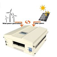
Years of technology accumulation mppt wind-solar hybrid charging inverter 500kw wind-solar hybrid inverter
-
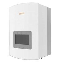
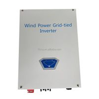
Jinlang wind turbine inverter 3KW-5kW grid-connected inverter has TUV certificate
-
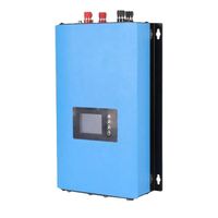
1000W/2000W Wind Power Grid-connected Inverter Wind Power Grid-connected Inverter Wind Turbine Generator
-
3KW 5KW 10KW Grid-connected MPPT Controller & Inverter Wind Turbine Controller Wind-solar Complementary Controller
-
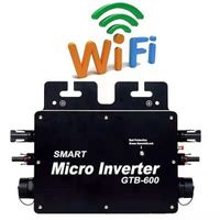
600w solar system micro inverter supplier
-
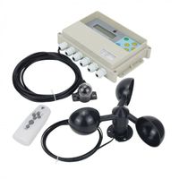
Dual Axis Solar Tracker Controller Automatic Solar Tracking with Remote Wind Sensor
-
300-600w 3 phase dc12-30v, 24-60v to AC110v/230v grid connected wind inverter for 12v and 24v wind system with brake
-
2KW 3.6KW 12V 24V Single Phase Grid Connected MPPT Hybrid Solar Wind Pump Inverter for Solar Power System
-
Inverter invt solar inverter 7kw hybrid controller wind energy solar hybrid controller
Other Products
-
$10.00 / piece