- Products
- Products
- Companies
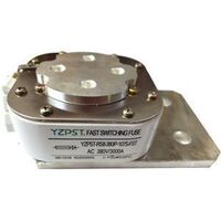
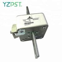
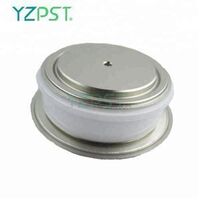
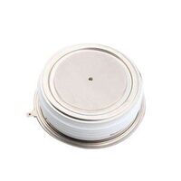
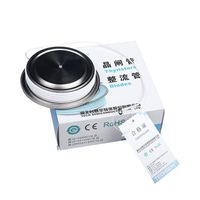
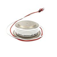
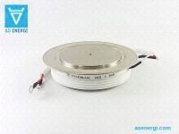
Phase Control Thyristor Scr DCR604

-
Supplier: Yangzhou Positioning Tech. Co., Ltd. -
Region: Jiangsu, China -
Contact: Mr John Chang -
Price: $11.00 / >=2 pieces -
Min. Order: 2 pieces
| Brand Name: | YZPST; | Single package size: | 50X33X22 cm; |
| IRRM / IDRM: | 15mA - 30mA; | Model Number: | YZPST-DCR604; |
| Application: | phase control rectifier; | Package Preview: | https://sc01.alicdn.com/kf/HTB1rgvpaXY7gK0jSZKzq6yikpXaP.jpg_640x640.jpg; |
| Mounting force: | 3.6 - 11.1 kN; | VTM: | 2.3V; |
| VDRM / VRRM: | 2000V; | IT(AV): | 600A; |
| ITSM: | 7200A - 7500A; | Packaging Detail: | Phase Control Thyristor Scr DCR604 1. Anti-electrostatic packaging 2. Carton box 3. Blister packaging; |
| Place of Origin: | Jiangsu China; | IT(RMS): | 940A; |
| VRSM: | 2100V; | Single gross weight: | 6.0 KG; |
| Product name: | Phase Control Thyristor Scr DCR604; | Selling Units: | Single item; |
| Weight: | 70g; |
 DCR604SE2121
HIGH POWER THYRISTOR FOR PHASE CONTROL APPLICATIONS
Features:
. All Diffused Structure
. Center Amplifying Gate Configuration
. Blocking capabilty up to 2000 volts
. Guaranteed Maximum Turn-Off Time
. High dV/dt Capability
. Pressure Assembled Device

Parameter | Symbol | Min. | Max. | Typ. | Units | Conditions |
Average value of on-state current | IT(AV) |
| 600 |
| A | Sinewave,180o conduction,Tc =65oC |
RMS value of on-state current | ITRMS |
| 940 |
| A | Nominal value |
Peak one cPSTCle surge (non repetitive) current |
ITSM |
| 7500
7200 |
| A
A | 8.3 msec (60Hz), sinusoidal wave- shape, 180o conduction, Tj = 125 oC 10.0 msec (50Hz), sinusoidal wave- shape, 180o conduction, Tj = 125 oC |
I square t | I2t |
| 235000 |
| A2s | 8.3 msec and 10.0 msec |
Latching current | IL |
| 800 |
| mA | VD = 24 V; RL= 12 ohms |
Holding current | IH |
| 400 |
| mA | VD = 24 V; I = 2.5 A |
Peak on-state voltage | VTM |
| 2.30 |
| V | ITM = 2000 A; Duty cPSTCle £ 0.01%
|
Critical rate of rise of on-state current (5, 6) | di/dt |
| 400 |
| A/ms | Switching from VDRM £ 1000 V, non-repetitive |
Critical rate of rise of on-state current (6) | di/dt |
| 150 |
| A/ms | Switching from VDRM £ 1000 V |
ELECTRICAL CHARACTERISTICS AND RATINGS (cont’d)
Gating
Parameter | Symbol | Min. | Max. | Typ. | Units | Conditions |
Peak gate power dissipation | PGM |
| 200 |
| W | tp = 40 us |
Average gate power dissipation | PG(AV) |
| 5 |
| W |
|
Peak gate current | IGM |
| 10 |
| A |
|
Gate current required to trigger all units | IGT |
| 300 150 125 |
| mA mA mA | VD = 6 V;RL = 3 ohms;Tj = -40 oC VD = 6 V;RL = 3 ohms;Tj = +25 oC VD = 6 V;RL = 3 ohms;Tj = +125oC |
Gate voltage required to trigger all units
| VGT |
0.15 | 5 3
|
| V V V | VD = 6 V;RL = 3 ohms;Tj = -40 oC VD = 6 V;RL = 3 ohms;Tj = 0-125oC VD = Rated VDRM; RL = 1000 ohms; Tj = + 125 oC |
Peak negative voltage | VGRM |
| 5 |
| V |
|
Dynamic
Parameter | Symbol | Min. | Max. | Typ. | Units | Conditions |
Delay time | td |
| 1.5 | 0.7 | ms | ITM = 50 A; VD = Rated VDRM Gate pulse: VG = 20 V; RG = 20 ohms; tr = 0.1 ms; tp = 20 ms |
Turn-off time (with VR = -50 V) | tq |
| 200
| 125 | ms | ITM = 500 A; di/dt = 25 A/ms; VR ³ -50 V; Re-applied dV/dt = 20 V/ms linear to 80% VDRM; VG = 0; Tj = 125 oC; Duty cPSTCle ³ 0.01% |
Reverse recovery charge | Qrr |
| * |
| mC | ITM = 500 A; di/dt = 25 A/ms; VR ³ -50 V |
* For guaranteed max. value, contact factory.
THERMAL AND MECHANICAL CHARACTERISTICS AND RATINGS
Parameter | Symbol | Min. | Max. | Typ. | Units | Conditions |
Operating temperature | Tj | -40 | +125 |
| oC |
|
Storage temperature | Tstg | -40 | +150 |
| oC |
|
Thermal resistance - junction to case | RQ (j-c)
| 0.045 (1) | 0.055 (2) |
| oC/W | Double sided cooled * (1) @ 2000 lb.; (2) @ 800 lb. |
Thermal resistamce - junction to case | RQ (j-c) | 0.090 (1) | 0.110 (2) |
| oC/W | Single sided cooled * (1) @ 2000 lb.; (2) @ 800 lb. |
Thermal resistance - case to sink | RQ (c-s) |
| .030 .060 |
| oC/W | Double sided cooled * Single sided cooled * |
Mounting force | P | 3.6 | 11.1 |
| kN |
|
Weight | W |
|
| 70 | g |
|
OUTLINE

Customer Reviews


-
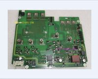
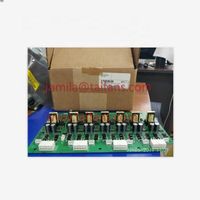
original inverter G120 new PM240 22-30KW drive plate A5E03894522 A5E01162134-001 A5E03894521

-
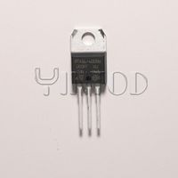
Youshang chip thyristor 600V TO-220 original BTA16-600BWRG
-
KK300A 2000V beauty machine fast switching thyristor
-
factory oven TECHSEM brand KK1500A thyristor 1800V
-
200A 1500A 2500V 3000V SCR Thyristor Controller Price
-
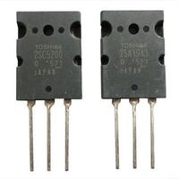
2SA1943 triode original TRANS NPN 230V 15A TO-3PL
-
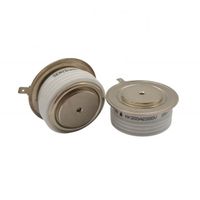
Phase Control Thyristor 6000A, 6300A, type T173-6300 SCR (200V – 400V)
-
Supply brand new original Korean ekoweiss inverter one-way thyristor/thyristor 20a800v TO-220 package bt152-800r
-
BTA416Y BTA416Y-800B TO-220 New original triode thyristor bidirectional SCR 800V 16A
-
New original 130B6016 DT 7 176F8626 130B6856 130B6016 DT 5 drive control board gate drive plate coating
Other Products
-
$150.00 / piece
-
$50.00 / piece
-
$13.00 / piece
-
$0.24 / piece
-
$0.12 / piece
-
$0.25 / piece
-
$0.16 / piece
-
$32.00 / piece
-
$115.00 / piece