- Products
- Products
- Companies
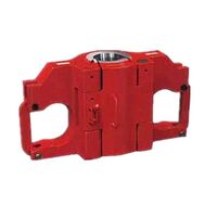
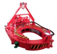
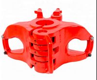
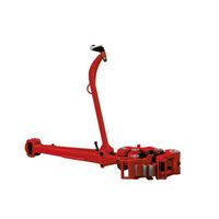
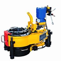
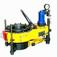
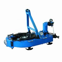
API 7K KHT13625 Teda Hydraulic Casing Power Tong for oil casing grabbing sizes from 2 3/8" to 13 5/8"

-
Supplier: Dongying Qixiang Import & Export Co., Ltd. -
Region: Shandong, China -
Contact: Ms Eve Liu -
Price: $20000.00 /set -
Min. Order: 1 set
| Warranty: | 1 year | model: | KHT13625 |
| Applicable industries: | Mechanical repair shops, energy and mining | Processing type: | forging |
| Local service location: | Egypt, Canada, United Kingdom, United States, Italy, Germany, Brazil, Saudi Arabia, Indonesia, Pakistan, India, Mexico, Russia, Thailand, Malaysia, Australia, Morocco, Kenya, Argentina, South Korea, Chile, Colombia, Algeria, Sri Lanka, Romania , South Africa, Kazakhstan, Ukraine, Tajikistan | Health status: | new |
| port: | Shanghai Port | Showroom location: | Egypt, Canada, UK, USA, Italy, France, Brazil, Saudi Arabia, Indonesia, Pakistan, India, Mexico, Russia, Morocco, Argentina, Korea, Chile, Colombia, Algeria, Romania, South Africa, Kazakhstan, Ukraine, Uzbekistan ,Australia |
| Type of machine: | Drilling tool | Supply capacity: | 85 sets per month |
| type: | Dentsu | Package preview: | |
| use: | drilling | brand: | TEDA, TEDA |
| Origin: | Chinese mainland) | payment terms: | L/C, T/T, Western Union |
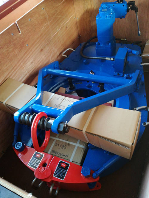
| Packaging Details: | Standard export packing or as your request | Material: | Carbon steel |
| Certification: | API |
KHT13625 Hydraulic casing power tongs
1. introduce
KHT13625 casing power tongs are used for loading and unloading casing operations in oilfields. The labor intensity of workers is greatly reduced, the quality of screw connection is improved, and the occurrence of accidents caused by improper casing operation is reduced. Electric pliers also have the following features:
Open type, it is convenient and quick to enter and slide out of the working position, and the overall clamp head has high strength and rigidity.
Double swing jaws, easy to assemble and disassemble.
The brake belt assembly is easy to operate and easy to maintain and replace.
Open gear support structure for increased strength and rigidity.
Full hydraulic mode and mechanical shifting.
The shell is made of high-strength steel plate to increase strength. The casting process of the jaws is precise, beautiful and generous.
With hydraulic torque indicator and installation interface, it is convenient to realize computer management.
The hydraulic safety device of the safety door is adopted, and the safety performance is good.
The torque range is large, which can meet the requirements of larger torque.
1.Specification
2.1. Jaws can be used for shell size 4″-13 5/8″
We provide four common jaws: 5 1/2″, 7″, 9 5/8″, 13 3/8″; others: 4″,
4 1/2″, 7 5/8″, 8 5/8″, 10 3/4″, 11 3/4″, 12 3/4″, 13 5/8″ Jaws can be configured according to customer requirements
2.2. Opening size 355.4 mm (14 inches) 2.3. Clamp speed
| High gear: | 30 | Rotating speed | |
| low profile: | 5 | Rotating speed | |
2.4. Rated torque | High gear: | 8.4 | kN.m (6200ft.lbs) | |
| low profile: | 42 | kN.m (31000ft.lbs) | |
2.5. Rated pressure | 16 MPa (2320 psi) | |||
2.1 2.6. work process | 150 | L/min (40GPM) | ||
2.7. Hydraulic power unit | flow | 160 L/min (50GPM) | ||
| pressure | 20 | MPa (2900 psi) | |
| Motor Power | 37 kW | ||
2.8. Dimensions (L×W×H) 1508×857×1194 mm (59″×34″×47″)
2.9. Weight 619 kg (1670 lbs) (including spring lifter assembly)
3. Operation
To ensure reliable operation of the tong, the tong must be properly hung. The hydraulic hoses must be properly connected and the following instructions for starting the tong must be followed:
3.1.Jaw installation (See below):

To install the jaws, remove the two jaw pivot bolts from the cage plate. Place the jaws one at a time between the upper and lower cage plates with the jaw roll pins facing up. Align the holes in the jaws with the matching holes in the cage plate and insert the jaw pivot bolts.
3.2.fitter
3.2.1.Thread
The tongs should be suspended by 5/8" diameter wire rope high enough in the derrick to ensure easy handling and maneuvering of the tong. One end of the rope should pass through the pulley. The other end should be knotted in the derrick ,A dead line is formed by a reaction force of about 13kN-18kN to keep the tongs balanced. If you can’t tie a knot on the derrick, you need to use the TEDA double spring spreader assembly. The spring hanger allows the tong to compensate the sleeve when threading Downward movement of the tube.
3.2.2.hydraulic hose
Hydraulic hoses can be attached to the pliers when the power unit is not running or the hydraulic pump is disconnected. By using a 1" high pressure hose and a 1-1/4" return hose, the possibility of error when interchanging high pressure supply and return hoses is eliminated. These hose fittings are self-sealing and care should be taken to ensure a complete engagement to prevent partial closure of the check valve in the fitting.

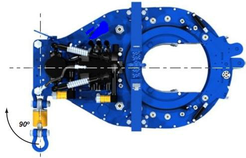
3.2.3.backup line
A 5/8" or larger wire rope is recommended as a tong backup line. It should be securely attached to the load cell on the rear of the tong and tied to a suitable anchor. To ensure accurate operation of the load cell and torque gauge , the top line should be connected with the tongs at a 90-degree angle and in the same horizontal plane (square and horizontal) (see the figure below):
3.3 Through operation
3.3.1 Startup procedure
Note: Before starting the power unit, make sure the door is closed and securely locked to ensure the safety of the operator.
Use the starting procedure recommended by the powerplant engine operator's manual. Before starting the engine, checks should be made to ensure that the lubricating oil level in the engine and the hydraulic oil level in the hydraulic tank are correct. Open the bypass valve on the hydraulic system. Check all pressure and return hose connections to make sure they are secure.
NOTE: If these hoses are not tightly connected, oil flow will be stopped or restricted and the following faults will occur
May happen:
a. If the pressure supply hose restricts or stops flow, it will cause high pressure in the powerplant hydraulic system, which will activate the hydraulic governor and accelerate the engine to maximum RPM.
b. If return line flow is stopped or restricted, it will cause high pressure on the power unit hydraulics
system, causing the engine to accelerate to maximum RPM and possibly causing the motor seal to fail.
After checking the hoses, start the engine and let it idle until it warms up. About 10 minutes after the powerplant engine is started and the hydraulic oil is circulating, slowly close the bypass valve, this will allow the oil to circulate through the hose and to the pliers. (Cycling pressure should not exceed 200 PSI.) Put the tong shift lever in low and rotate the tong slowly forward, then reverse through the throttle lever. Once this is done and the proper size jaws installed, the tongs are ready to run the pipe.
3.3.2.direction and speed control
A four-way valve assembly controls direction, rotational speed and torque output. Turn clockwise to push the valve handle forward, and turn counterclockwise to pull the valve handle in the opposite direction. Velocity in either direction is proportional to the distance the valve handle travels from the center or neutral position (see diagram):


3.3.4.Composition of the shell
In order to properly assemble the sleeve joint, the following procedure can be used:
a. Place the pliers around the cannula.
b. Fully close and lock the door.
C. Put the dowel pin in the hole to make up.

a. Shift the transmission to high gear.
b. Push the throttle handle forward slightly until the sleeve threads begin to tighten.
c. As the casing threads begin to turn up, push the valve handle all the way forward until the tongs begin to stop.
d. Release the throttle.
e. Shift transmission to low range.
F. Engage the throttle and comp housing to the desired torque.
g. Reverse the jaws to loosen the jaws and rotate until the table gear is aligned with the door opening.
H. Open the door and remove the pliers from the pipe.
3.3.5.Casing rupture
In order to properly remove the bushing joint, the following procedure can be used: Place pliers around the bushing.![]()
![]()
![]()
![]()
b. Fully close and lock the door.
b. Put the support pins in the holes (see picture below) to remove


Shipping period: 30 days
![]()
4. Our services
-
api drill pipe lifts 7k oil rig lifts

-
API 7K Q3-3/8~12-3/4-75 Type B Manual Pliers
-
Oil pipe power tong API 7K TEDA hydraulic power tong
-
Elevator type BD
-
API DDZ Drill Pipe Lift
-
API Spec 8A/8C Skid Series Oil Well Drilling Elevator
-
API 8A/8C DDZ Oil Well Drill Pipe Elevator
-
API ZQ127 TEDA hydraulic drill pipe power tongs for TEDA wellhead
-
API 8A SLX lift for drilling
-
API 7K TQ340/35Y Oil Drilling Casing/Hydraulic Power Clamp Torque Meter For Sale

Other Products
-
$200.00 / piece
-
$2000.00 / set
-
$34000.00 / set
-
$1500.00 / set
-
$14000.00 / set
-
$1000.00 / set
-
$7500.00 / set
-
$150.00 / set
-
$14000.00 / set
-
$10.00 / piece