- Products
- Products
- Companies
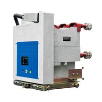
High Voltage Electrical Switchgear Ground Fault Indicators Short Circuit Indicators

-
Supplier: Zhejiang Greenpower I&e Co., Ltd. -
Region: Zhejiang, China -
Contact: Ms Annie C -
Price: $145.00 /set -
Min. Order: 1 set
| Humidity range: | ≤95% | place of origin; place of origin: | Zhejiang, China |
| Ground wire length: | 3.5m | Ground current: | 20A, 30A, 40A, 50A, 60A±10% delay 40s |
| power supply: | Lithium battery 3.6V/2.45Ah | port: | Ningbo, Shanghai or any port in China |
| brand: | GP, green energy | Short circuit current: | 100A~1000A |
| Protection class: | Main controller: IP40, sensor: IP65 | Cutting hole size: | 91x44mm |
| Packaging Details: | with carton | temperature range: | -25 to +70 degrees |
| payment terms: | L/C, D/P, D/P, T/T | Master size: | 95x50x80mm |
| model: | GPJ-3100 | Output relay: | 120 VAC 1 Amp, 30 VDC 2 Amps |
| Package preview: |
Applications
GPJ-3100 series short circuit and ground fault indicator is designed for real-time detection and indication of short circuit and ground fault. It is suitable for line monitoring in ring network cabinets, overhead lines, power cable wiring, box transformers and other similar places. According to the alarm signal displayed by the indicator light, when a short circuit or ground fault occurs in the line, the staff can quickly find out and cut off the faulty area, so that the system can quickly restore the power supply to the non-faulty area, saving time and improving efficiency.
Conductive fiber length | 4m |
Auto reset time | 7s, 2hrs, 4hrs, 8hrs |
l High reliability MCU, low power consumption during monitoring.
l Passive sensor
l Long life lithium battery power supply
l Three-phase independent detection
l The short-circuit signal is transmitted by optical fiber, isolated from high voltage, with good safety and high reliability.
l Self-locking output relay.
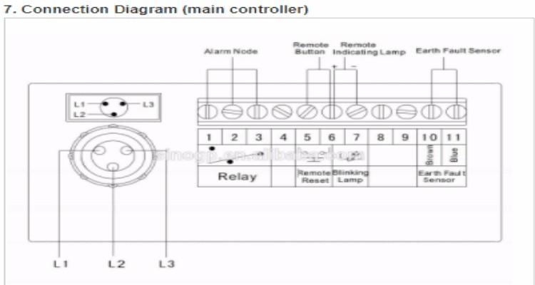
1. Short-circuit alarm: The short-circuit sensor monitors the high-voltage cables in operation in real time. When the line current reaches or exceeds the short-circuit current setting value, the sensor sends an alarm signal to the main controller through the optional optical fiber. After the main controller receives the signal, it sends out an alarm signal accordingly (the indicator light flashes quickly).
2. Ground fault alarm: When the line current reaches or exceeds the ground fault current setting value, the ground fault sensor sends an alarm signal to the main controller. After the main controller receives the signal, it sends out an alarm signal accordingly (the indicator light flashes quickly).
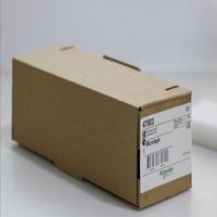
3. Remote transmission alarm signal: The main controller drives the corresponding relay remote transmission signal according to different alarm signals.
4. Automatic reset: When the device sends out an alarm signal, if no one resets within the preset time, it will automatically reset.
5. Manual reset: When the device sends out an alarm signal and the fault is eliminated (the indicator light flashes slowly), press the RESET button on the main controller to release the alarm state or remotely reset through the REMOTE RESET terminal.
6. Self-inspection: Under normal circumstances, press and hold the RESET button for 2 seconds, the system enters the self-inspection state, the short-circuit and ground fault indicators flash quickly, and the output relay pulls in, indicating that the working state is normal. After the indicator light flashes slowly for 2s, short press the RESET button, and the system enters the normal state.
7. Battery: When the battery voltage is lower than 3V, the indicator light will flash quickly to remind the user to replace the battery in time. If the system is underpowered, the alarm can continue to indicate for more than 60 days.
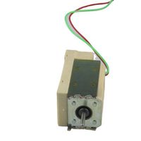
6.1 Main Controller
Push the main controller into the slot through the opening on the front panel of the switch cabinet (as shown in Figure 5-1).
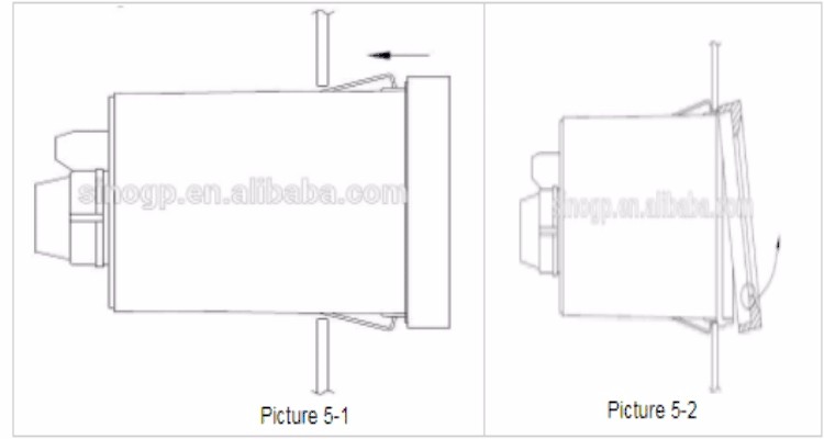
Cutting hole size: 91*44mm
Gently pull down the front lower frame of the main controller (as shown in Figure 5-2), and take out the front panel of the main controller, you can set the following parameters:
To set the ground fault alarm current:
Set the ground fault alarm current value by adjusting the five DIP switches behind the front panel. The detailed correspondence is as follows:
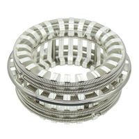
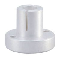
6.2 Short circuit fault sensor
The short-circuit sensor should be installed on the phase cable of the power supply line. Tighten the captive screw and insert the optional optical fiber into the bottom of the connector to prevent the sensor from sliding and causing the cable to loosen or fall off.
Cable diameter: D15mm~40mm
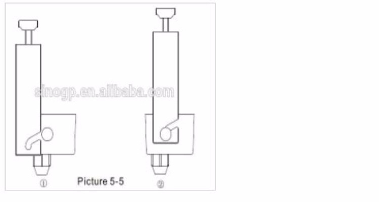
1) Adjust the position of the U-shaped iron so that the chute is inserted into the iron core slot.
2) Gently pull the U-shaped iron so that the inclined bottom is completely inserted into the iron core groove, and at the same time fix the upper fastening screw on the top of the U-shaped iron to prevent the U-shaped iron from loosening.
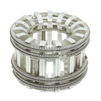
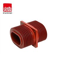
6.3 Ground fault sensor
Secure the 3 phase wires with straps and tighten the setscrews. The ground wire at the top of the sensor must be re-routed through the sensor and then connected to the ground wire. The ground fault sensor is connected to the main controller through the ground wire.
Cable diameter: D60mm~100mm
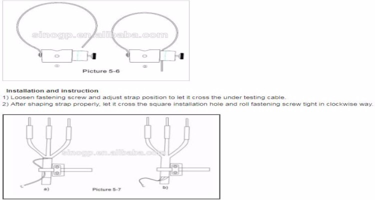
notes:
a) The ground shield cable on top of the ground fault sensor must pass through the ground fault sensor and be connected to ground.
b) The ground shield cable at the bottom of the ground fault sensor cannot pass through the ground fault sensor. (As shown in Figure 5-7).
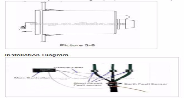
6.4 Battery Replacement
Open the main controller panel, take out the battery panel below, disconnect the battery connection socket, and loosen the fastening screws to replace the battery (as shown in Figure 5-8).
-
The new Micrologic 6.0E control unit is suitable for CompactNS and MasterpactMT

-
China tempered high voltage glass electrical insulator manufacturer
-
DSN-AMY 12kV switch cabinet indoor electrical cabinet AC220v magnetic lock
-
2000A 2500A Strapped Tulip Contacts and Copper Contacts for Vacuum Circuit Breaker Assemblies
-
1000A 1250A Plum Blossom Contact Factory Contact Finger For Vacuum Circuit Breaker Tulip Contact China Stainless Steel Chronograph
-
Shunt release frame circuit breaker accessories three-lock two-button control unit door frame etc.
-
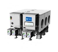
FKG2S GE Generator Breaker GE GCB
-
VI Down Exit Base for VCB VI Assemblies GPB402 VCB Assemblies
-
Epoxy Resin Insulated 10kV Busbar Support With Wall Wrap For High Voltage Switchgear
-
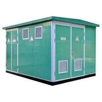
Outdoor three-phase 11KV 15KV 33KV compact pavilion type substation

Other Products
-
$35.00 / set
-
$2200.00 - $2500.00 / set
-
$1950.00 - $2050.00 / set