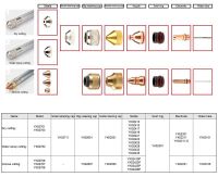
YK330 YIKUAI PLASMA CUTTING TORCH AND CONSUMABLES
- 120.00 1 - 10 pieces
YK330 YIKUAI plasma torch and consumable
Current:40~400A
Quality cutting: 6~40mm
Maximum cutting:60mm
Features:
The most core technical feature of the YK330 torch is its dual water-cooling design for both the electrode and nozzle. Compared to traditional single water-cooling or air cooling, this design significantly reduces the temperature of key consumable parts, thereby greatly extending their service life.
At the same time, it optimizes the gas path compression ratio design, resulting in more concentrated arc energy and a more stable arc column. This produces a straighter, smoother, and finer cut surface, reducing the amount of subsequent grinding work required.
Model | YK330 | |||
Working current: | 30~400A | |||
Arc pilot method: | HF | |||
Quality cutting(carbon steel): | 6~40mm | |||
Maximum cutting(carbon steel): | 60mm | |||
Cooling method: | Electrode & Nozzle double water cooling | |||
Rated duty cycle: | 100% | |||
Rated working air pressure: | 0.45~0.60Mpa | |||
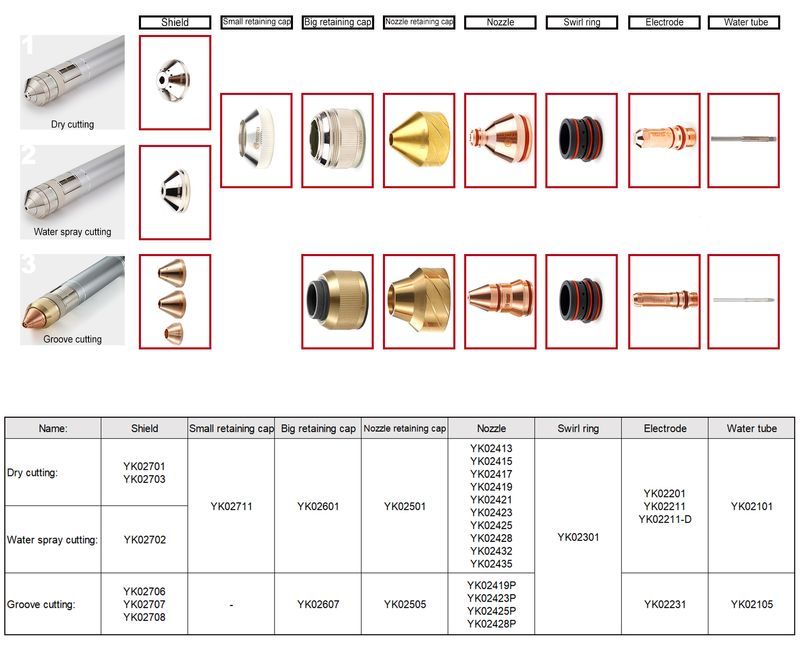
Cutting applications: | 1)YK330 with YK02701 shield general cutting; 2)YK330 with YK02702 shield water spray cutting; 3)YK330P model groove cutting; | |||
Nozzle size:
| Hole Dia | Series No. | Cutting thickness | Current |
1.3mm | YK02413 | 3~7mm | 60~120A | |
1.5mm | YK02415 | 6~12mm | 80~120A | |
1.7mm | YK02417 | 8~14mm | 100~120A | |
1.9mm | YK02419 | 12~20mm | 150~180A | |
2.1mm | YK02421 | 16~20mm | 200~220A | |
2.3mm | YK02423 | 20~25mm | 220~250A | |
2.5mm | YK02425 | 20~30mm | 250~280A | |
2.8mm | YK02428 | 25~35mm | 300~320A | |
3.2mm | YK02432 | 30~40mm | 320~350A | |
3.5mm | YK02435 | 40~50mm | 320~380A | |
Note:1)The 1.3mm and 1.5mm size arc compression much please adjust suitable gas pressure, and big gas pressure will disperse arc and difficult arc pilot success; 2)The working current as suggestion parameters please basic on actual demand adjust it; | ||||
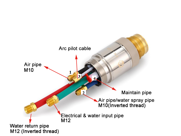
Torch interior connector size: | 1)Electrical & water input pipe: M12X1.5mm; 2)Water return:M12X1.5mm(reverse thread); 3)Cutting & Shielding gas: M10X1.0mm; | |||
Torch cable length: | Standard length 7.1M, extended length can be 25M; | |||
Torch cable connector size: (for connection power source and can be customized) | 1)Electrical & water input cable: M16X1.5mm; 2)Water return cable:M10X1.0mm; (or M16X1.5mm reverse thread); 3)Ga & Electrical cable: M14X1.5mm; | |||
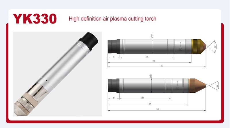
Torch size: | φ50X325mm | |||
Torch weight: | 1.60KGS | |||
Please change the nozzle and electrode when the following situation occurs:
1.Cutting gap become larger
2.Cann't start the arc
3.Cutting area color getting much abnormal
4.Arc distinguish
5.Cutting speed suddenly decrease
6.Cutting nozzle getting seriously burned
7.Cutting nozzle melted on the work-piece
8.The electrode center sunk up to 2mm
The torch interior connector size:
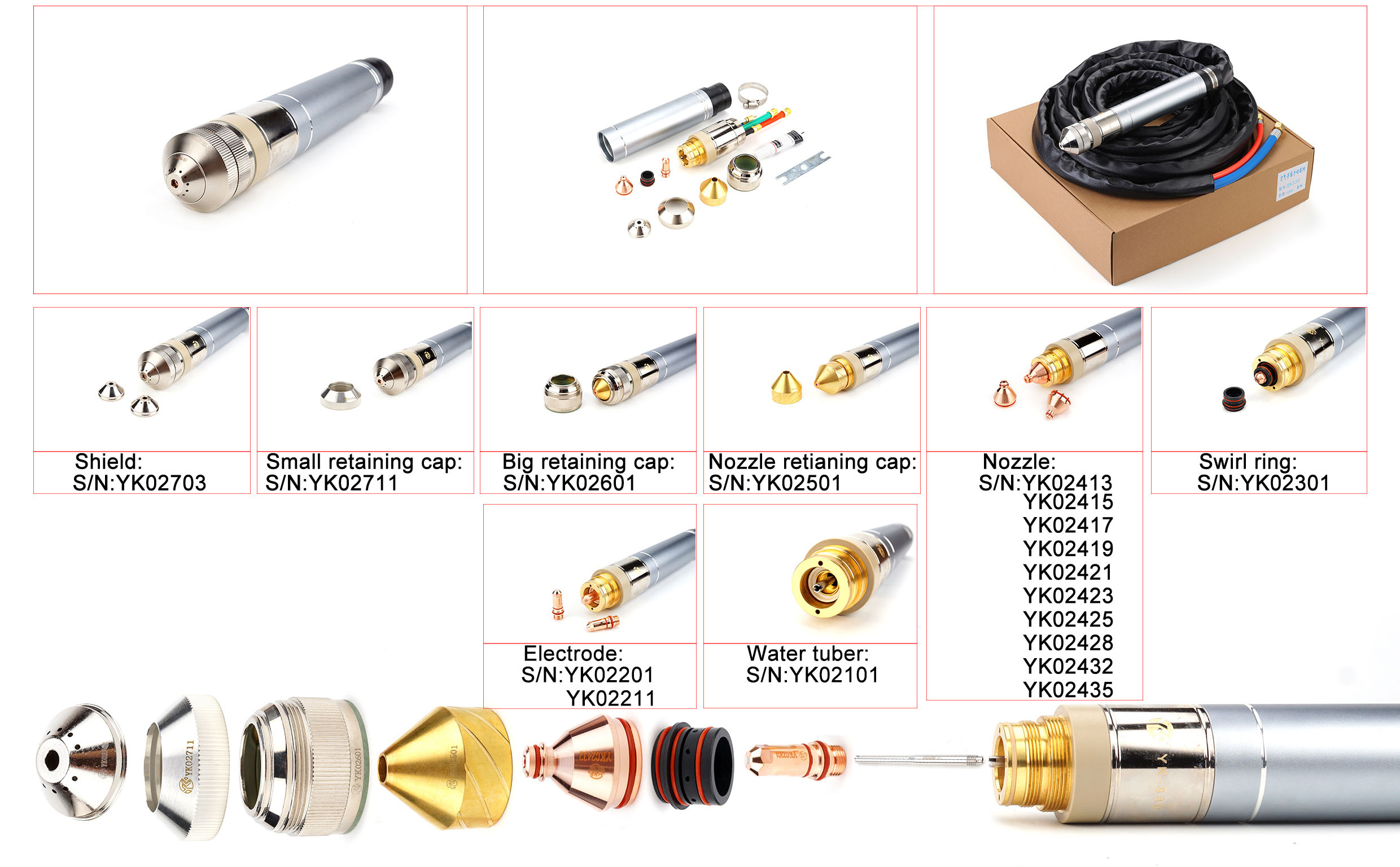
Steps for inspecting and replacing torch consumables:
1.Turn off the plasma cutting power switch and ensure the torch cooling system of the plasma power supply has stopped working.
2.Remove the consumable parts from the torch body and check for worn or damaged components. After removing the consumable parts, they must be placed on a clean, dry, oil-free surface. Dirty consumable parts may cause torch malfunction.
3.If the consumable parts are worn or damaged, replace them. Please refer to the "Installing Consumables and Wear Parts" section in the consumable replacement process image above.
4.After installing the consumable parts, ensure the torch is perpendicular to the workpiece. Then, first turn on the plasma power supply and open the test gas switch on the control panel for about ten seconds. At this time, the gas from the torch head can blow away any moisture remaining in the nozzle and swirl ring. Close the test gas switch, and finally turn on the cooling water tank. Once the water flow indicator light on the plasma control panel illuminates, normal cutting operations can proceed.
Instruction for use:
1. Properly install the water inlet/outlet, gas lines, and high-frequency cable according to the power supply requirements. Pay special attention to the water flow direction; incorrect connection may result in reduced water flow and pipeline blockage.
2.The lower middle part of the outer casing is the clamping area. Insulating components must be present at the clamping point to prevent the casing from connecting to the ground.
3.Before cutting, check the gas and water supply to ensure stable gas and water pressure within the allowable range. The gas must be clean and dry; the coolant must be free of suspended particles and other impurities, with temperature and flow rate within the allowable range.
4.Install the electrode, nozzle, and other components in the correct order. Apply lubricating grease to the sealing rings, check that the silicone seals are intact, inspect components for signs of wear, and replace or repair them promptly if necessary.
5. In the event of gas leakage, water leakage, failure to initiate the arc, reduced cutting quality, excessive component wear, or similar issues, contact the equipment maintenance personnel promptly. Do not operate the equipment while it is faulty.
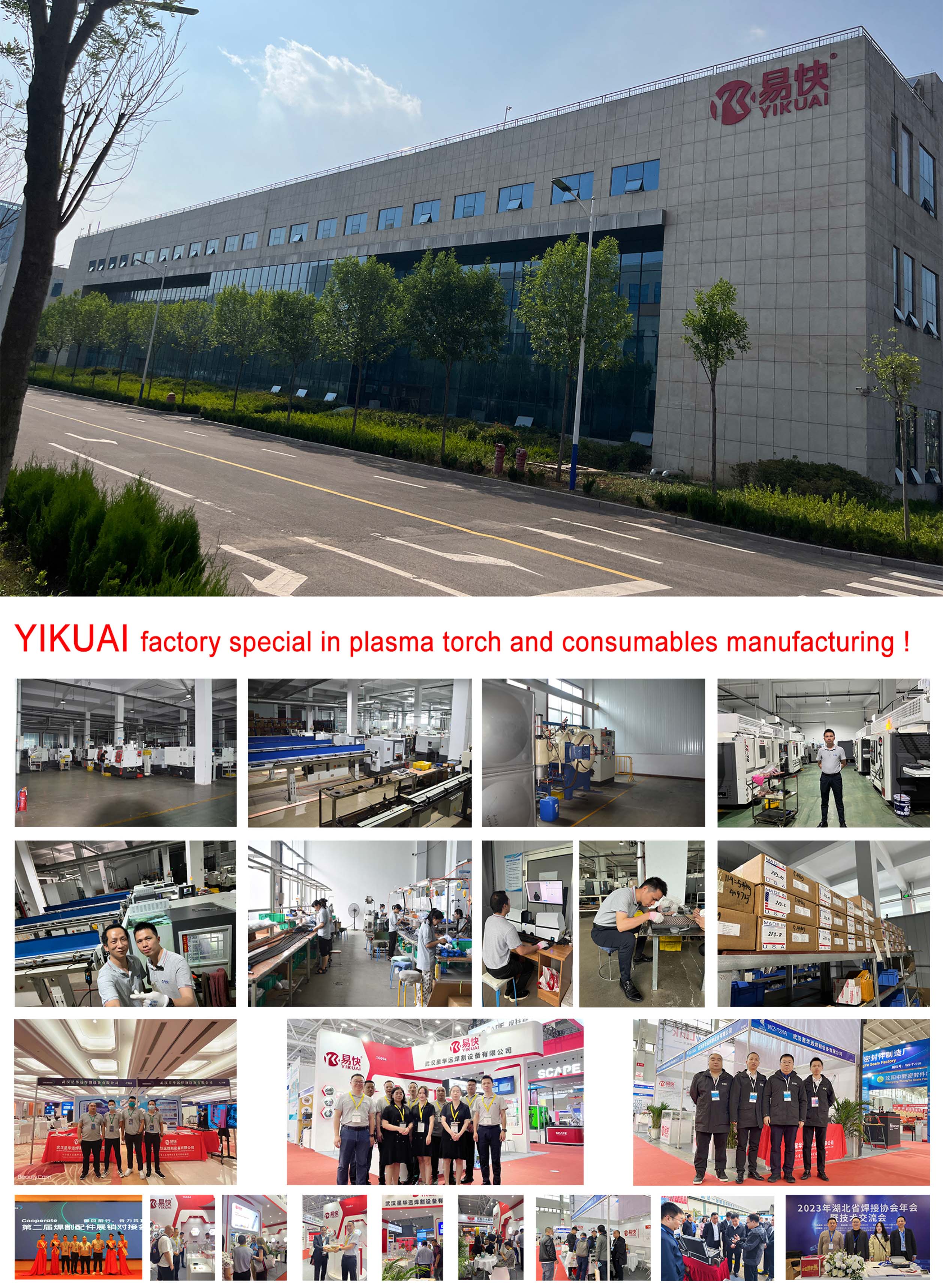
YIKUAI factory introduce:

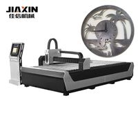
CNC Plasma Cutting Machine Metal Sheet Cutting Machine
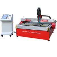
TNC-3015 Cheap High Precision Desktop CNC Plasma Flame Cutting Machine
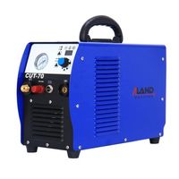
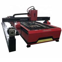
1500*3000 2000*4000mm China metal cutting/cnc plasma table/plasma cutting machine with rotation
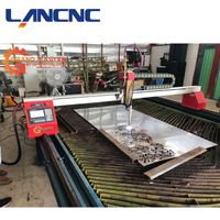
Mini CNC Plasma Gantry CNC Plasma Cutting Machine Optional Worktable Competitive Price 3000*5000 Auto CAD Offer 300
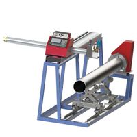
High precision 1630 CNC plasma pipe cutting machine for metal pipe
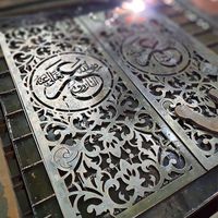
cnc plasma cutting machine portable cnc plasma cutting machine
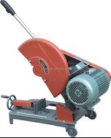
Sell CE Steel Cutting Machine Electric Profile Cutting Machine and J3G3 Cutting Machine