- Products
- Products
- Companies
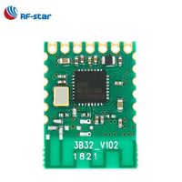
CC2538 CC2592 PA Zigbee Wireless Module

-
Supplier: Shenzhen Duoweisi Tech Co., Ltd. -
Region: Guangdong, China -
Contact: Ms danna yang -
Price: $1.00 /piece -
Min. Order: 1 piece
Product details
| country of origin: | China | port: | Shenzhen |
| payment terms: | T/T, Western Union, MoneyGram, PayPal | brand: | Dovis |
| model: | CC2538 CC2592 | application: | CC2538 CC2592 PA Zigbee Wireless Module |
feature
1. CC2538 chip. ARM core, rich hardware resources;
2. The frequency is 2.4GHz, the communication distance is long, the anti-interference ability is strong, and the transmission rate can reach 250kbps.
3. Good wireless performance, low harmonics, fully meet the certification requirements;
4. Low power consumption, easy to control to low power consumption mode;
5. Small size, light weight, size 21×32m, the main board adopts welding method;
6. All high-quality components are used, and the crystal oscillator adopts MOTO and MICRO crystal oscillators. Reliability is very good.
7. Provide two antenna connection methods: PCB antenna and IPEX antenna connection seat.
Pin description:


Sensitivity: -103.5dBm
Output power: +20dBm
Input gain: 12dB
Noise: 4 decibels
Emission current: <175mA
Receive current: 30mA
Sleep current: 0.4uA
Working voltage: 3.3V
Transmission distance: 600m
Data rate: 250Kbps
Number of channels: 16
Antenna: PCB or IPEX
Temperature range: -40℃~80℃
Module size 21×33m pin pitch 1.27mm

explain:
1. Optional external IPEX-SMA antenna or PCB antenna;
2. PC2, PC3, and PD2 are used for CC2592 control and are not exported; PD4 and PD5 are not exported
3. The pin signal is marked on the back of the module;
Pin Dimensions and PCB Diagram

PA Control Pin Description
(1) The pins of PC2, PC3, and PD2 are for the PA, and they are not connected to the module IO, so do not use them
(2) PD4 and PD5 are not elicited.

Instructions for use
1) It is recommended to set the output power of CC2538 to +3dBm, at this time the output power of the whole module reaches about +20dBm.
2) The module can be directly fixed or soldered to the product's PCB. If using a PCB antenna, under the PCB antenna
There must be no traces or copper cladding. There should be no metal or magnetic material around the PCB antenna.
3) The standard SZ12 module comes with PCB printed board antenna, including IPX antenna base, and the default transmitting antenna is PCB
antenna. Users can choose IPEX-SMA double-ended feeder, external SMA antenna, this mode is suitable for
The module is installed in a strong shielding shell, and the antenna is placed outside the shell. When using this mode, it is necessary to disconnect the
Open the PCB antenna connection to direct the RF signal to the IPEX socket.
The power supply voltage is +3.3V, and the output current is guaranteed to be >175mA.
Minimum system circuit:

J1 is the emulator interface, the emulator XDS100V3 produced by our company. R is not disconnected when the emulator is used for power. If using 2-wire cJTAG interface, disconnect R7, R8, use 4-wire JTAG interface, do not disconnect R7, R8..
C is the power supply filter capacitor, its value is generally 33~100uF, it is best to use a tantalum capacitor..
The reset circuit is already in the module, and no external components are required, but if the RST lead is long, it is recommended to add a filter circuit close to the module.
VIEW MORE
You may like
-
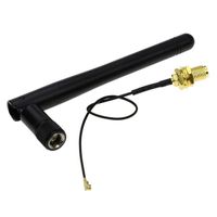
Wholesale Antenna - 2.4g Bluetooth WiFi Module Foldable ZigBee Antenna

-
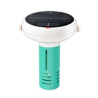
7-in-1 residual chlorine meter/pH/TDS/EC/ORP/salinity/TEMP aquaculture swimming pool fish tank Zigbee solar water quality monitor
-
ZigBee 3.0 20 dBm RF Signal Repeater Router Amplifier Work with Echo Plus SmartThings Hub Tuya eWeLink Hue zigbee2mqtt
-
Wifi Gateway Wireless Long Distance IOT Blue-Tooth Support Wifi Gateway Alexa Voice Control PST-JMWBG1
-
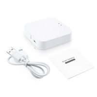
Tuya Smart Gateway Hub Smart Home Bridge WiFi ZigBee APP Wireless Remote Control Alexa Google Home
-
Tuya Smart Home WiFi 3 in 1 38K IR Wireless Remote Gateway with BLE Mesh+ZigBee Controller Multi-Function Via Alexa Google Home
-
SMATRUL Tuya Zigbee 3.0 remote control smart life gateway hub wired automation support scene linkage Google Home
-
Zigbee/5G/WIFI/Mobile/Bluetooth low-cost test shielding box
-
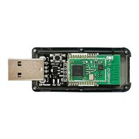
Home Automation FCC EFR32 2.4G Zigbee Wireless Programmable Module
-
Tuya Zigbee Hub LAN Gateway Bridge APP Smart Life ZigBee 3.0 Wire Hub Sensors Working with Alexa Google Home