- Products
- Products
- Companies
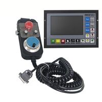
Digital Dream NCH-02 4 Axis 125Khz CNC Pendant Motion Controller for CNC Router Milling Engraving machines

-
Supplier: Shenzhen Digital Dream Numerical Technology Co., Ltd. -
Region: Guangdong Province, China -
Price: $114.50 / >=10 pieces -
Min. Order: 10 pieces
| Payment Terms: | T/T,Western Union; | Core Components: | PCB+ software; |
| After Warranty Service: | Online support; | Video outgoing-inspection: | Not Available; |
| No. of Outputs Ports: | 5; | Controller Kinds: | Handheld Motion Controller; |
| Dimension(L*W*H): | 30x26x9; | Applicable Industries: | Machinery Repair Shops,Manufacturing Plant,Advertising Company; |
| Showroom Location: | None; | Lanuage: | Chinese/English; |
| No. of Inputs Ports: | 8; | Place of Origin: | Guangdong China; |
| Package Preview: | ; | Certification: | CE; |
| Position Signal Type: | Pulse+Direction; | Supply Ability: | 1000 Piece/Pieces per Month; |
| Axis: | 4 Axis; | Condition: | New; |
| Local Service Location: | None; | Marketing Type: | Ordinary Product; |
| Machinery Test Report: | Not Available; | Application: | Milling,Router,Engraving machines; |
| Max.Output Frequency(Khz): | 125; | Packaging Detail: | Carton Package; |
| Weight: | 0.7; | Spindle Control: | Analog Voltage Output 0-10V; |
| Brand Name: | Digital Dream; | After-sales Service Provided: | Online support; |
| Warranty: | 1 Year; | Port: | Shenzhen; |
| Power Supply: | 24VDC,1A; | Control Signal: | Optocoupler Drain open signal; |
Digital Dream has a 10 years history in the numerical control industry, specializing in the research, development and production of various CNC (Computer Numerical Control) systems. DigitalDream aims to combine high quality and high reliability with affordability. We produce 1 axis to 6 axes CNC system.
Thank you for choosing digital dream’s motion controllers.With a lots of examples and charts,this manual will describe the features,functions and every operations of our controllers.Pls read this manual carefully before any assembling and using.Incorrect handling can result in injury and damage to persons and engraving machine.Pls keep the manual carefully for convenient to read it at any time in need.
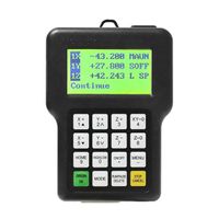
NCH02 is very professional 3-5 Axis CNC Motion Controller which is based on embedded system.NCH02 operates as a standalone system with handheld Pendant without the need of a computer,and with a pendant,it makes users very convenient to opreate the machines.Our controller adopts Embedded Operating System,by which the controller will never get virus-infected.And the controller adopts look-ahead algorithm by which the the controller can read more ahead 30-lines G-code than the operating.All the features guarantees high precision,accuracy and reliability.And the size is very small,oepreation is very easy,very suitable for all size of Engraving machines,Milling machines and cutting machines and so on.
1. Products Brief Features:
1) Max. 5 Axis,3-5 Axis Optional;Max. 125Khz per axis;
2) 2-4 Axis linear interpolation,any 2 axis circular interpolation;
3) 5 opto isolated digital outputs,8 opto isolated digital inputs;
4) Analog spindle control 0-10V spindle control (can be modified as PWM output);
5) 24VDC power input, minimum 1A;
6) 3.5 inches TFT screen, resolution ratio: 480x320;19 user keys;
9) USB flash disk support for G code file input;
10) The control system can preview the process path before machining,and it makes the system more steady,working smoothy and precise;
11) Support the Standa rd MPG or the NVMPG which Digital dream made;
12) Acceleration/Deceleration Mode: S curve;
13) Support un-limited size file for machining;
14) Manual/Automatic machining function;
15) Support the operation to Start a G code from a specific line;
16) Supporting Homing,Go to Zero,workpiece origin position saving;
17) Supporting downloading and uploading all the parameter setting of the controller.
NCH-02 Size:
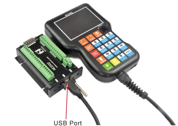
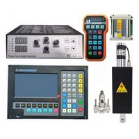
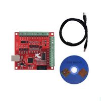
The NCH02 motion controller contains the handheld motion controller,wiring board,and USB transmission cable.
The handheld motion controller and wiring board are communicated by 1.5 Meter USB transmission cable which is shielding twisted-pair cable to avoid interference.
Picture 1-1 shows the appearance and size of NCH02 Pendant.
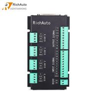
Picture 1-2 shows the appearance and size of NCH02 Wiring Board.
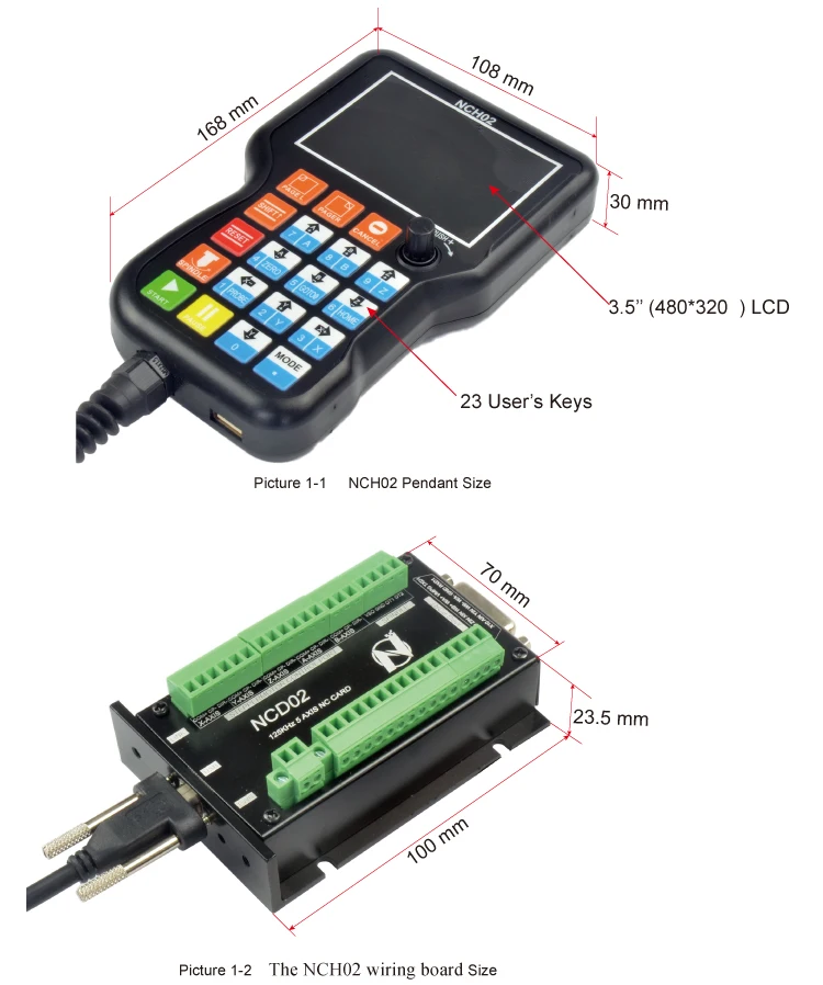
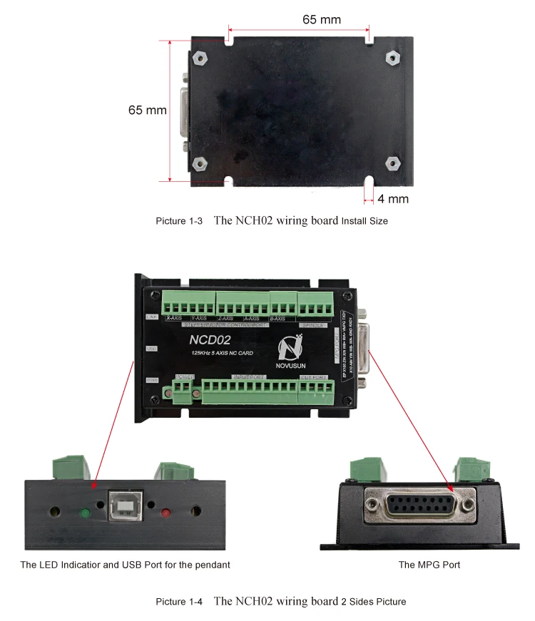
Picture 1-3 shows the Installation size of NCH02 Wiring Board.
Picture 1-4 shows the 2 side pictures of NCH Wiring Board.The one side is for the MPG interface;and the other side is the LED indicators and USB port for the communication with the NCH02 Pendant Controller.
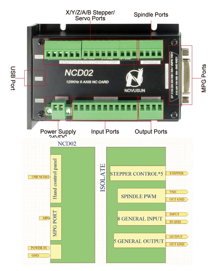
2. Product Wiring Overview
The circuit switching wiring board provides screw terminals for power (24VDC), input signals, spindle control, pulse and direction for X/Y/Z/A/B stepper/ servo drives, MPG, input and output ports as well as an USB input.
Please see the reference following in detail.
There are two LED indicatiors,the red one is for the power,the green one is for the communications with the NCH Pendant controller.
As the picture shows, the wiring section of the controller has Stepper/Servo Ports,Spindle Control Ports,MPG ports,Output and Input Ports,and Power supply Ports,as well as USB ports.
The Inside power solution in the field of the Industrial automation is always very complicated, there is a lot of the GND, now we descript the structure of the power structure as below:
The power structure,main power supply input ,MPG module and Power and USB port share common GND, stepper control module and Input&Output module and Spindle control module share common GND, between the two sector there is photoelectric isolation. Inside of the board, there is GND as common-, no need to connect external power supply.
1) USB Communication Port
2) Main power supply port
The Power Supply Input voltage is 24VDC, and the power is not less than 20W. The positive and negative connection of the power supply see as the silk printing.
3) The Input Ports
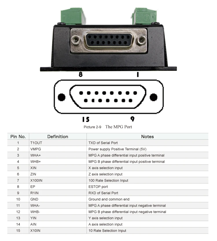
The MPG port the DB15 Female terminals next to the USB port. The users need to weld the MPG cables into the DB15 Male terminal,and plug-in to the MPG port of the controller MPG port.
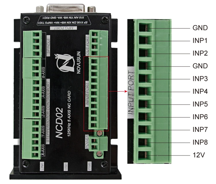
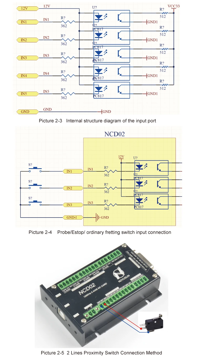
As the Picture 2-2 showed,Inputs ports has already defined.The Users can use them as E-stop,Probe,limited/Home functions and so on.The ports is a common negative interface,which can be connected with a micro switch,a 2 line proximity switch or a NPN type 3 line proximity switch.All the ports are isolated.And the internal structure is as following Picture 2-3.
And the E-stop,Micro switch,2 line proximity switch connection methods refered to Picture 2-4.
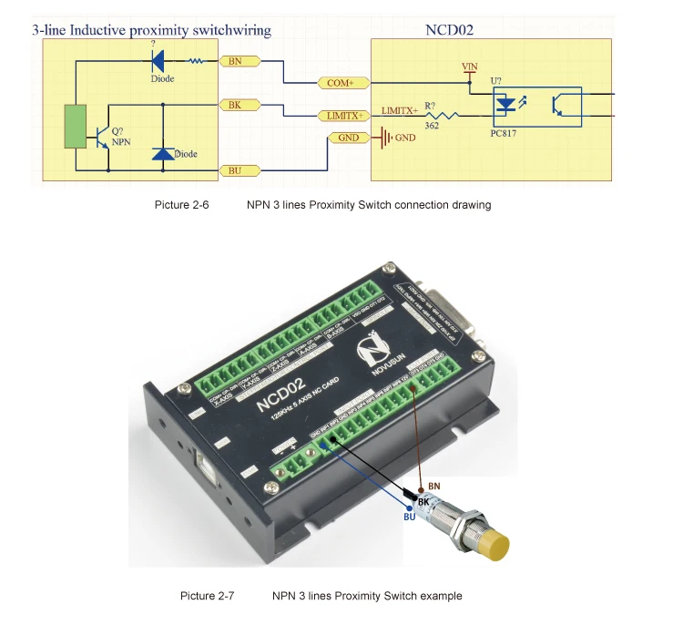
3 lines Proximity Switch connection method as following Picture 2-6 shows. Brown cable connect with 12V,Black cable connect channel, blue cable connect with GND1.
3 lines proximity switch only NPN type is avaiable for the NCH02.
4) The Output Ports
As the Picture 2-8 shows,the interface is an open-ground interface,which can be absorbed not more than 50mA current.The relay with a absorption current of no more than 50mA can be driven directly. If it's more than 50mA, and it is recommended to use a current amplification, for example ULN2803 chip.

5) The MPG Ports
The MPG interface Pin order as following:
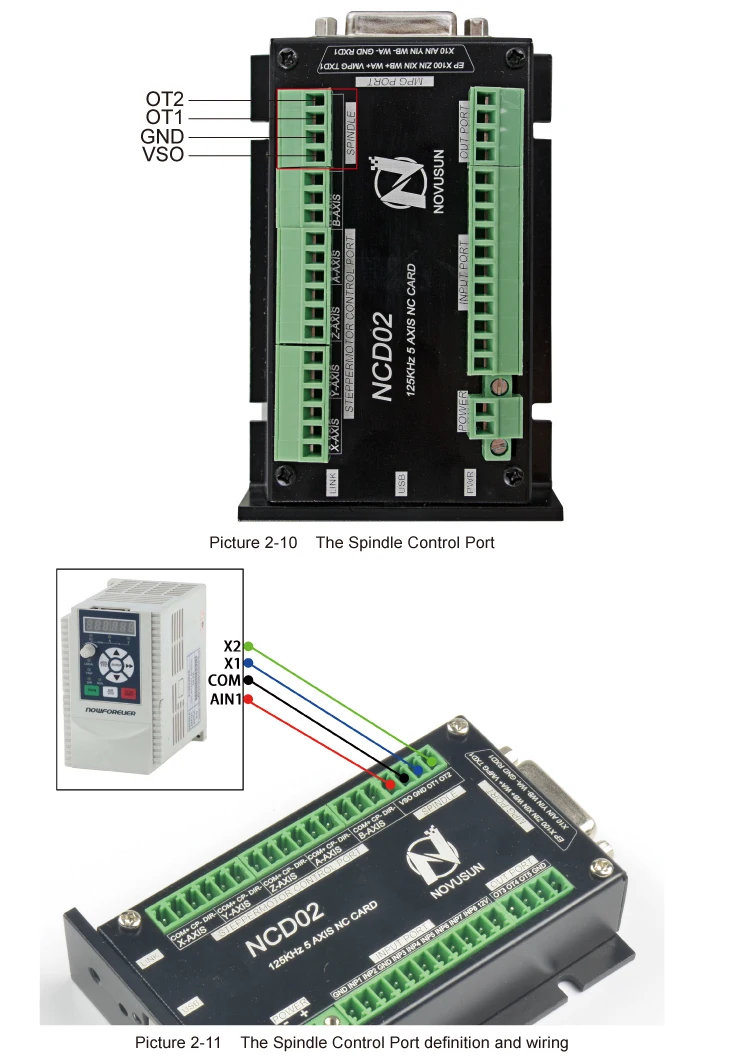
6) The Spindle Control Port
The Picture 2-10 showed interface definition is VSO/GND/OT1/OT2.
The VSO is the 0-10V analog output, OT1/OT2 digital signal output, spindle control output interface and spindle inverter connection methods as Picture 2-11. VSO/GND/OT1/OT2 are respectively connected with the inverter AIN1/COM/X1/X2, where AIN1 is the input speed signal;COM is Comman Ground;X1 and X2 are configured to forward and reverse Turning.
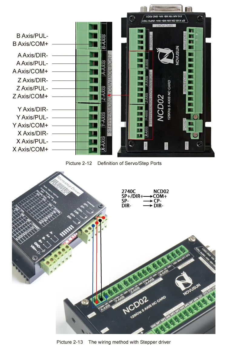
7) The Servo/Stepper Port
The following Picture 2-12 shows the definition of Servo/Stepper Ports.There are 5 axis X/Y/Z/A/B,each axis connection is common anode.Output signal voltage is 5V.
DIR is Direction Signal Output;
PUL is Pulse Signal Output.
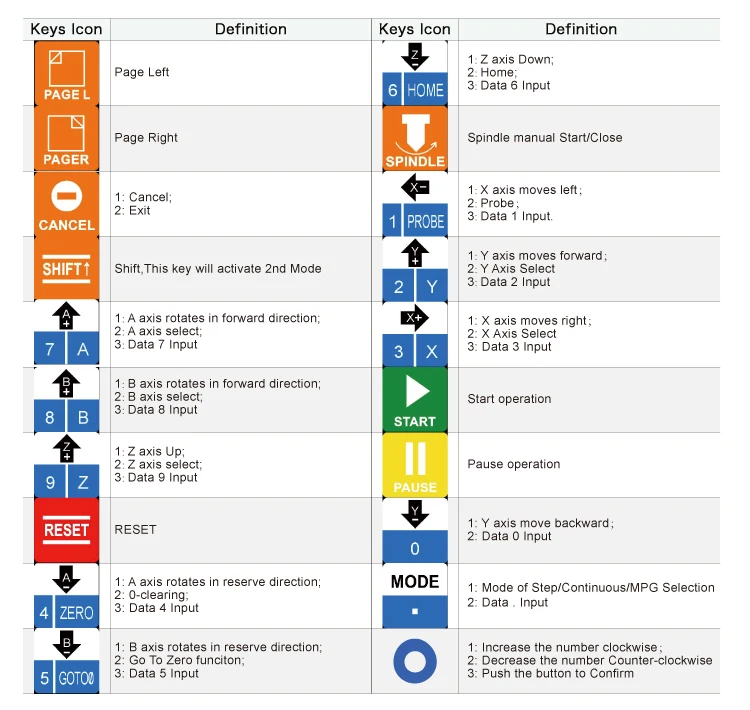
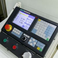
3. Handheld Controller Keyboard Definition
4. Motion Controller Software Description
1) The Main Page

1. Feed status:Manually Position the machine at any position:
The Picture 4-1 shows the main page in CONT mode,which is continuous mode.There are Continuous mode,Step Mode and MPG mode for options by pressing the key MODE to shift the 3 different mode.
2. Operation Status: It shows the working status of Controller :
The Operation Status column displays the working status of the controller.There are 4 different status:
RESET/READY/JOG/RUN
By Pressing RESET ,The controller status shift between READY and RESET status;
Only When in READY status,By Pressing START , the controller will start to run a G-code,then the status turn to “RUN”.And during the operation by handheld controllers of Jog operation,the status turns to “JOG”MODE.
3. File status:It shows the G-code file information and U-disk
There will be 4 Status at File Status:No file Loaded;U-Disk Detected;U-Disk Removed;G-code file name:
No File Loaded:When the controller cannot detect a U-disk and cannot load a file;
U-Disk Detected:When the U-disk is inserted and controller can detect the U-disk;
U-Disk Removed:When the U-disk is removed;
G-code file name:When the G-code file is selected and the controller is running the G-code file,it will display the name of the G-code file.
4. Time display:This column shows the processing time of the G code operation.
Time keeping is halted during Pause.
Before the description from No.5,we’d like to explain the Rotary&Push Button. By this button,it can decrease or increase the values by turnning the button,and push it to confirm.
When we need to edit a value,for example,FRO or SRO or SJR value and so on,firstly select it and push the button,we can see the orignal values color is white and background is black,then we start to edit it by turning the button,the values’ background color becomes to Blue.After we edited the value,and we push the button to confirm it,the background turns to black color.Then Push the button again to exit the editting state.
This is the operation method for all the value editing.
5. FRO: FRO controls the Feed Speed.
The adjustment range is 0%~200%.By turnning the rotary button,adjust the value in 10% increments by each click.
6. SRO:SRO controls the Spindle Speed.
The adjustment range is 0%~200%.By turnning the rotary button,adjust the value in 10% increments by each click.The current spind speed #S=SRO*S(The fixed Spindle speed value)
7. SJR: SJR controls the jogging of the machine.
The adjustment range is 0%~100%.By turnning the rotary button,adjust the value in 10% increments by each click.The Current Jog Speed #HF=SJR*HF(The fixed Jog Speed)
8: Manual Jog Distance in Step Mode:
Each Axis can be jogged in defined distance.In Step Mode,you can define the increments by 0.01mm,0.1mm or 1mm.By turning the button,the values can be decrease or increase.
default Spindle Speed. The Default Spindle Speed can be changed, use the A- key to modify.
9: Feedrate:F stands for Feed Speed:
It is the minimum Feed speed value of the controller,can be adjust by Rotary button also.
If there is no F values in G-code file,the controller will run the file at the speed of Feedrate value,if there is F value in G-code file,the controller just run as the G-code file.
10: Real time Feed Speed:
F Real-time Feed Speed Value shows the current feeding speed when running a G-code.
F Real-time Feed Speed Value=FRO*F(The Feed speed fixd by G-code or controller)
11: Speed of spindle:
It is the Default Spindle speed value of the controller,can be adjust by Rotary button also.
If there is no S values in G-code file,the controller will run the file at the speed of Feedrate value,if there is S value in G-code file,the controller just run as the G-code file.
12: Real time Spindle Speed:
S Real-time Spindle Speed Value shows the current Spindle speed when running a G-code.
F Real-time Feed Speed Value=SRO*S(The Spindle speed fixd by G-code or controller).
13: M10/M11: Start/Stop of Lubrication
M10/M11 can adjust by rotaty button,or can run as the directive from G-code file.
14: M8/M9 : Start/Stop of Cooling
M8/M9 can adjust by rotaty button,or can run as the directive from G-code file.
15: M3/M4/M5: forward-rotating/Reverse-Rotating/Stop Spindle
M3/M4/M5 can adjust by rotaty button,or can run as the directive from G-code file.
16: Coordinate System
The Coordinate System Range is G54-G59,can adjust by rotaty button,or can run as the directive from G-code file.
17: Controller System Status
There are 7 different kinds status of the controller.Here we explain them as below:
18: The G-code Line that the Controller is Running
In the column,it shows the current G-code Line No. and G-code content.To Shift the G-code line,the users can can edit Line Value here.
19: The coordinate values of each axis under the current coordinate
The coordinate values of each axis under the current coordinate are displayed here.
20: The coordinate values of each axis under the mechanical coordinate
The coordinate values of each axis under the mechanical coordinate are displayed here.
2) The File Page Page
3) The CONFIG(Configuration) Page
4) Test and Diagnosis Page
These pages please read the NCH-02 User's Manual.
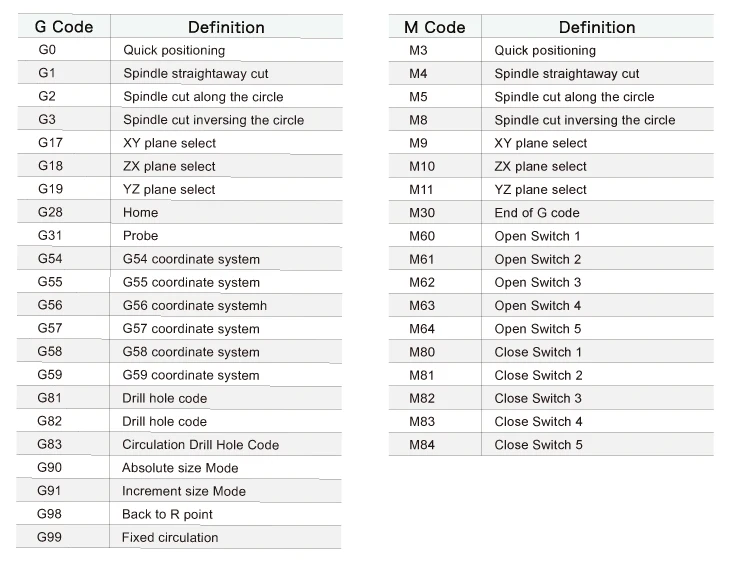
5. The G Code and M Code
As the following G code list and M code list shows,these G codes and M codes are supported by NCH02 Motion Controller.
Packaging material: Cardboard box with foam inside.
Shipping:
A. Normally it takes 3-5 business days worldwide shipping from China by Air/Express(DHL,FedEx,UPS,EMS etc.) without delay.
If you are in the long distance area, it might be a little longer. If your country has special import policy, please contact us in advance before confirming an order. In that case, we could negotiate a best shipping method for you.
B. We can arrange shipment by sea. Minimum CBM requirements to be 1 CBM.
C.You can inform of us to use your own carrier account No., if it is convenient for you.
1.The friendly English Version manual is provided for free.
2. We offer 24 hours technical support on-line or you can send us your specific problem directly by email.
3.Warranty: 1 year limited and professional long-term technical support.
4.Free training to make sure you master the operating of our products.
5. We accept OEM/ODM, but the MOQ of OEM/ODM is 100 sets.
-
F2100B plasma controller + lifter kit F2100B+F1621+JYKB-100-DC24V-T3+F1510T for plasma cutting machine cutting machine

-
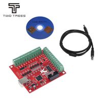
Dytrees CNC USB MACH3 100Khz output board mach3 board 4 axis motion driver interface controller
-
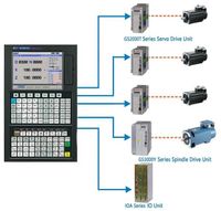
Absolute CNC remote control lathe and milling CNC servo system, similar to HNC and Fanuc
-
Reiz A11 DSP mobile phone repair service
-
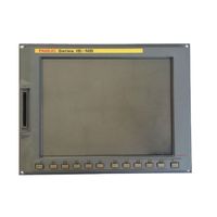
A02B-0321-B530 0i-Mate MD/TD CNC Fanuc machine tool original system controller
-
DSP Controller Accessory Richauto A11 A18 B11 B18 8IO Interface Board
-
Dytrees Hot Sale CNC USB MACH3 100Khz Breakout Board 4 Axis Interface Driver Motion Controller
-
A02B-0281-C071/C072 18i-MB/TB CNC Fanuc machine tool original system controller
-
Cheap portable cnc plasma flame sheet metal cutting machine prices
-
GSK 980TDc 5-axis CNC controller for lathe and turn-mill CNC systems

Other Products
-
$280.00 - $290.00 / piece